Lighting device

a technology secondary lens, which is applied in the direction of lighting and heating apparatus, lighting applications, fixed installations, etc., can solve the problems of poor heat radiation efficiency, adverse effects of lens arrangement and optical performance, and failure to facilitate precise arrangement of light emitting device packages. , to achieve the effect of improving heat radiation efficiency

Active Publication Date: 2012-03-15
SAMSUNG ELECTRONICS CO LTD
View PDF6 Cites 12 Cited by
  • Summary
  • Abstract
  • Description
  • Claims
  • Application Information

AI Technical Summary

Benefits of technology

[0015]An aspect of the present invention provides a lighting device capable of stably protecting a lens unit, that is, a secondary lens corresponding to an application field from external environments while having improvements in heat radiation efficiency.
[0016]According to an aspect of the present invention, there is provided a lighting device, comprising: a light source module mounted on a substrate; a lens unit provided on the light source module and including an accommodating groove accommodating the light source module; a housing unit accommodating the lens unit therein to protect the lens unit from an outside; a supporting unit fixed to the substrate and including a coupling hole having the housing unit coupled thereto to thereby support the housing unit; and a height adjustment unit allowing the housing unit to be vertically-movably coupled to the supporting unit and adjusting a height of the lens unit such that the height of the lens unit is varied.

Problems solved by technology

However, the direct attachment method may be disadvantageous in that the function thereof capable of protecting the light emitting device package and the secondary lens from external circumstances is defective.
Moreover, the pillar structure attachment method is a method of fixing a secondary lens by using a separate pillar-shaped device, and may be disadvantageous, in that the arrangement and optical performance of lenses may have adverse effects due to the deformation of the pillar-shaped device (deformation in a pillar shape).
In addition, the pillar structure attachment method may require an attachment area wider than a diameter of the lens, similarly to the direct attachment method, and in the pillar structure attachment method, the precise arrangement of the light emitting device package may not be facilitated due to the injection molding of the pillar.

Method used


Image

  • Lighting device
  • Lighting device
  • Lighting device

Examples


Embodiment Construction

[0035]Embodiments of the present invention will now be described in detail with reference to the accompanying drawings.

[0036]The invention may, however, be embodied in many different forms and should not be construed as being limited to the embodiments set forth herein. Rather, these embodiments are provided so that this disclosure will be thorough and complete, and will fully convey the scope of the invention to those skilled in the art.

[0037]In the drawings, the shapes and sizes of components are exaggerated for clarity. The same or equivalent elements are referred to by the same reference numerals throughout the specification.

[0038]A lighting device according to an embodiment of the present invention will be explained with reference to FIGS. 1 through 6.

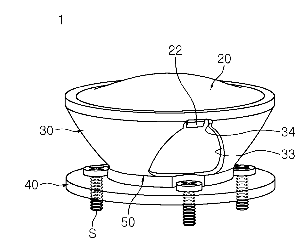
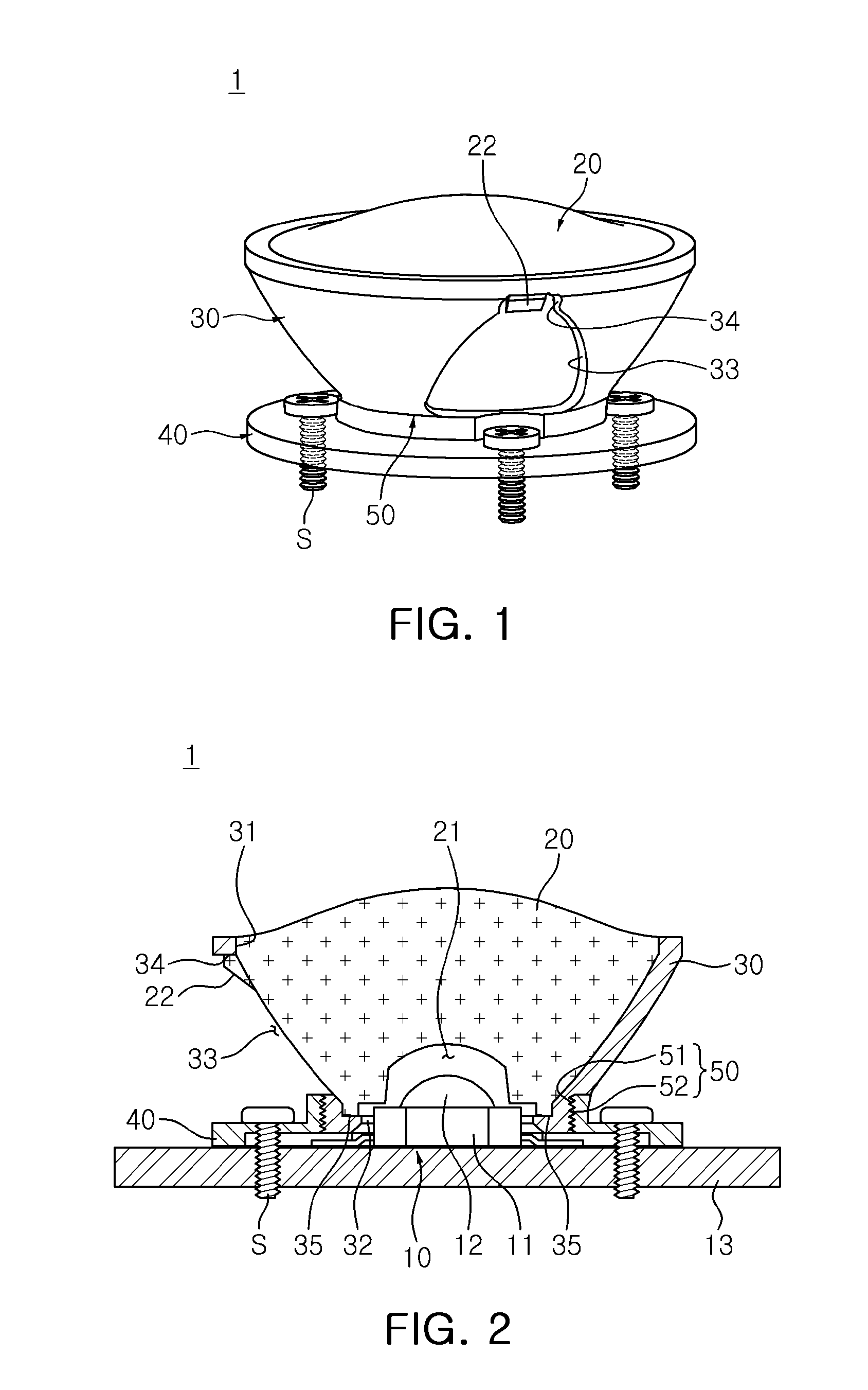
[0039]FIG. 1 is a schematic view of a lighting device according to an embodiment of the present invention. FIG. 2 is a schematic cross-sectional view of the lighting device shown in FIG. 1.

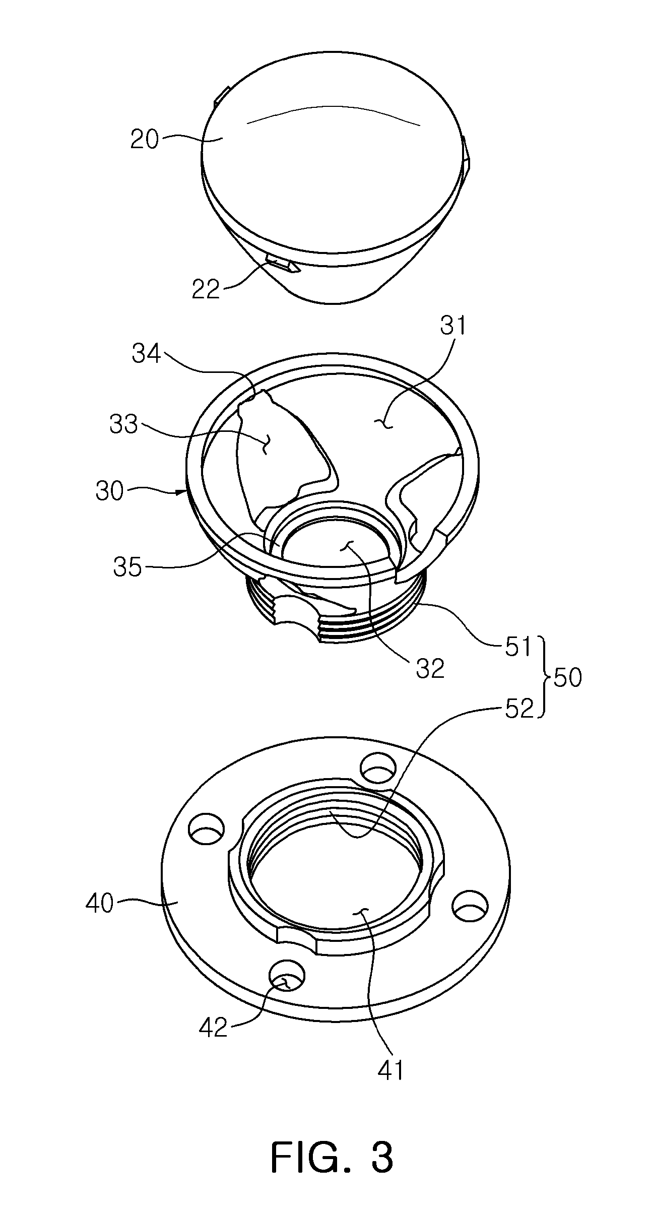
[0040]FIG. 3 is a schematic exploded pers...


PUM


Abstract

A lighting device is provided. The lighting device includes: a light source module mounted on a substrate; a lens unit provided on the light source module and including an accommodating groove accommodating the light source module; a housing unit accommodating the lens unit therein to protect the lens unit from an outside; a supporting unit fixed to the substrate and including a coupling hole having the housing unit coupled thereto to thereby support the housing unit; and a height adjustment unit allowing the housing unit to be vertically-movably coupled to the supporting unit and adjusting a height of the lens unit such that the height of the lens unit is varied.

Description

CROSS-REFERENCE TO RELATED APPLICATIONS[0001]This application claims the priority of Korean Patent Application No. 10-2010-0088407 filed on Sep. 9, 2010, in the Korean Intellectual Property Office, the disclosure of which is incorporated herein by reference.BACKGROUND OF THE INVENTION[0002]1. Field of the Invention[0003]The present invention relates to a lighting device.[0004]2. Description of the Related Art[0005]In general, a light emitting device package, including a light emitting device emitting light according to an application of an electrical signal thereto, has been widely used in various electronic products and mobile communications terminals, such as personal cellular phones, personal digital assistants (PDAs) and the like.[0006]Recently, with an increase in light emitting device efficiency, the range of applications of a light emitting device package has been extended, and a secondary lens has been required for various applications of a light emitting device package.[000...

Claims


Application Information

Patent Timeline
Patent Type & Authority Applications(United States)
IPC IPC(8): F21V99/00
CPCF21K9/30F21V14/06F21V17/02F21V17/12F21V29/507F21V5/04F21V5/045F21V29/504F21Y2101/02F21K9/20F21K9/69F21Y2115/10
Inventor PARK, HUN YONGKIM, BYUNG MAN
Owner SAMSUNG ELECTRONICS CO LTD
Why Eureka
Try Eureka