
Method for managing paths between a source node and a destination node within the data link layer, corresponding source node and table

a technology of data link layer and source node, applied in the field of managing paths between source node and destination node within the data link layer, corresponding source node and table, can solve the problems of inability to provide special solutions, difficulty in transmission of additional flow, and itself runs the risk of becoming saturated

Inactive Publication Date: 2012-03-15
FRANCE TELECOM SA
View PDF20 Cites 9 Cited by
  • Summary
  • Abstract
  • Description
  • Claims
  • Application Information

AI Technical Summary

Benefits of technology

[0028]This unique flow identifier in the network enables the simple and efficient management of the load, as the identifier can be communicated to all the nodes. In certain embodiments, a flow identifier can be allocated to a group of flows. For example, the sound and image of a video conference are two different flows, but it may be wished to allocated the same identifier to them in order be sure that they pass through the same path.
[0032]According to a second particular embodiment, said identifier can be obtained by concatenation of bits extracted from at least two fields of at least one packet of said flow, containing at least one of the pieces of data belonging to the group comprising an address of the source node, an address of the destination code, an identifier of a transport protocol for said flow, a source port of said transportation protocol for said flow in said source node, a destination port for said transportation protocol for said flow in said destination node. This embodiment is adapted to software implementation because it is less penalizing in terms of the time taken to write the flow identifier for each frame.
[0042]It is also possible to reallocate a preferred path when its load becomes lighter.

Problems solved by technology

These two prior art path selection techniques do not provide for any special solution in the event of an exchange of several distinct flows between a same source node and a same destination node.
In certain cases, for example if one or more flows are already being transmitted between the source node and the destination node, the transmission of an additional flow may be difficult for reasons of path overload.
In this case, in a situation of saturation or overload detected on a first path, all the flows will switch over to a second path, known as a backup path, which itself runs the risk of becoming saturated.
There is then a phenomena of oscillation (switching of all the flows from one path to another) and therefore of major deterioration of the quality of service.

Method used


Image

  • Method for managing paths between a source node and a destination node within the data link layer, corresponding source node and table
  • Method for managing paths between a source node and a destination node within the data link layer, corresponding source node and table
  • Method for managing paths between a source node and a destination node within the data link layer, corresponding source node and table

Examples


Embodiment Construction

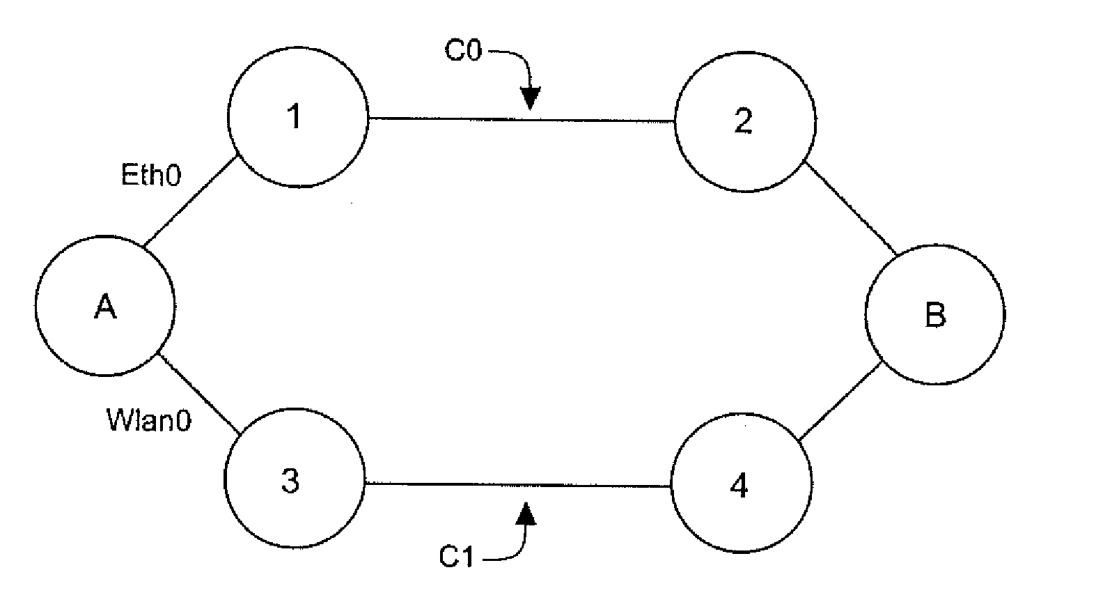
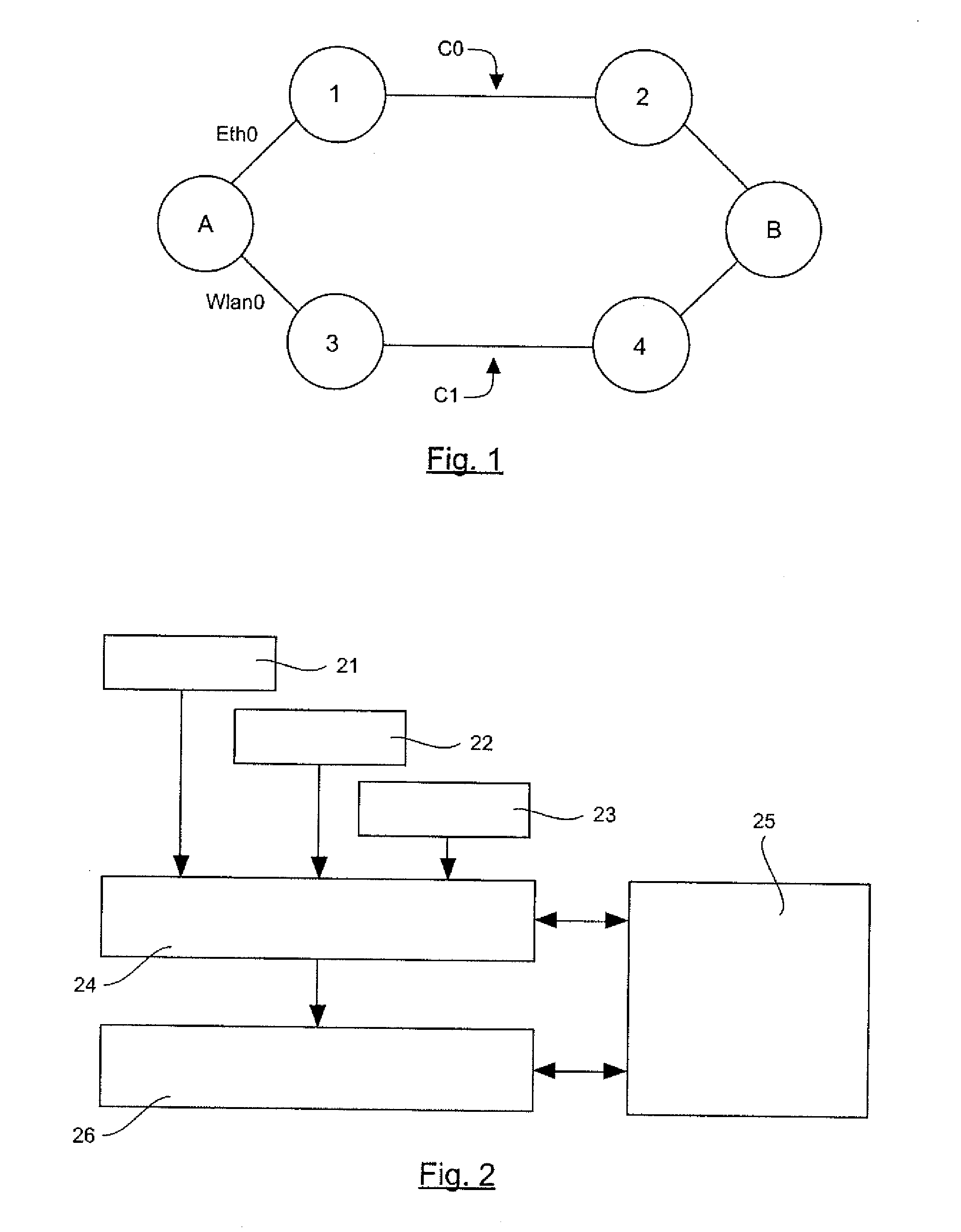
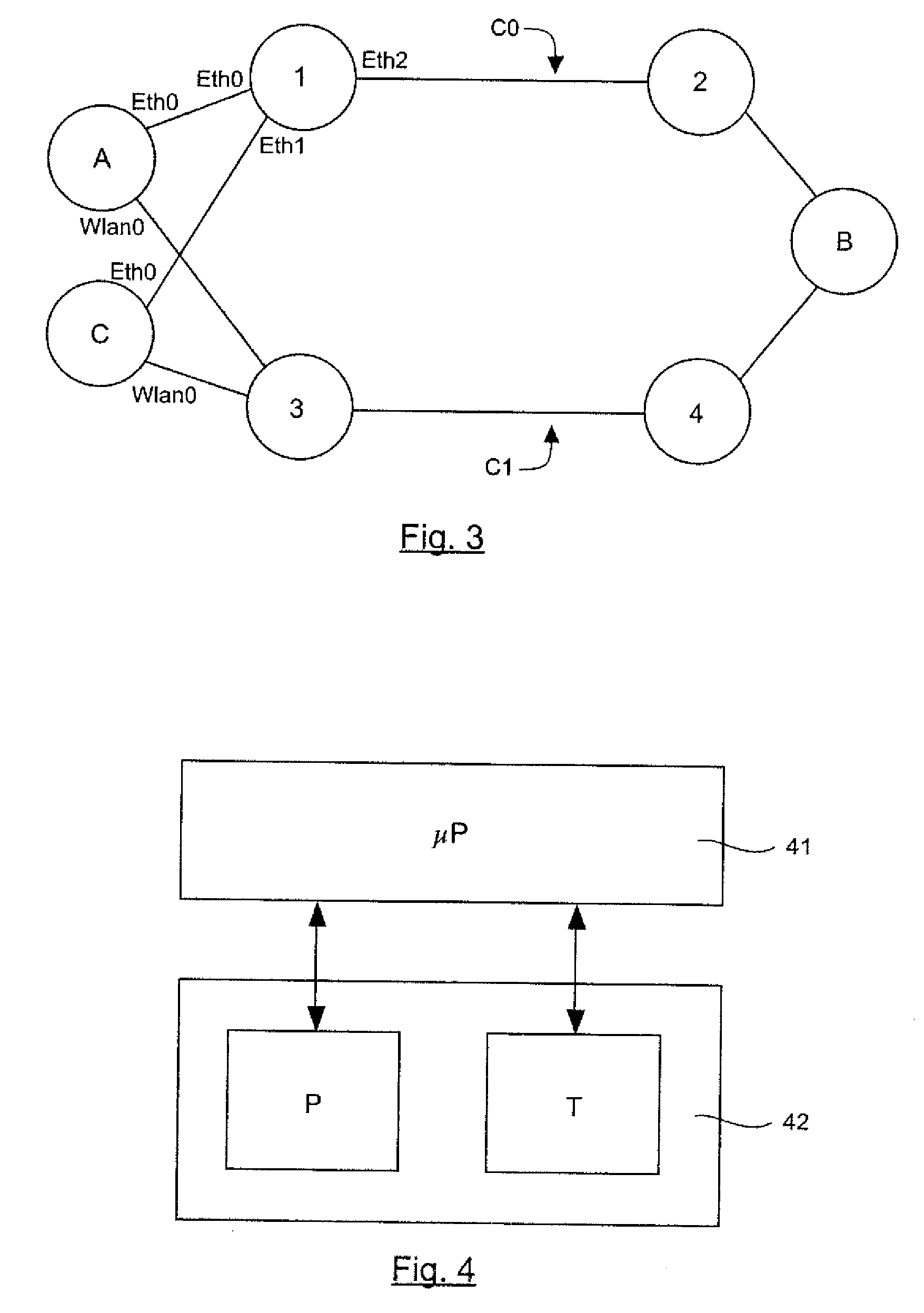
[0052]An embodiment of the invention therefore proposes a novel approach to the transmission of flows in the data link layer (level 2 of the OSI system) adapted to the mesh network, enabling the definition of several paths between a source node and a destination node. In particular, it may be a meshed Ethernet network or a multi-technology network, the nodes of which have at least two distinct interfaces, capable for example of respectively managing the Ethernet protocol, a Wi-Fi transmission or transmission by power link communications (PLC).

[0053]According to an embodiment of the invention, a solution is proposed enabling the management of multiple paths in the data link layer to distribute if necessary the flows to be transmitted between a source node A and a destination node B, especially as a function of their category.

[0054]The category of a flow may be a class of service representing the type of its content (video, audio). It may simply take into account a level of importance...


PUM


Abstract

A method is provided for managing paths between at least one source node and at least one destination node within the link layer in a mesh communication network including a plurality of intermediate nodes. At a given moment, at least two separate paths between the source node and the destination node are defined for distributing streams to be transmitted between the source node and the destination node. The method includes the following steps that are carried out in the source node: allocating a stream identifier to the streams; associating information representing a stream category to the streams; allocating one of the paths to one of the streams while taking into account the stream identifier and the stream category information.

Description

CROSS-REFERENCE TO RELATED APPLICATIONS[0001]This application is a Section 371 National Stage Application of International Application No. PCT / FR2010 / 051002, filed May 25, 2010, which is incorporated by reference in its entirety and published as WO 2010 / 136715 on Dec. 2, 2010, not in English.STATEMENT REGARDING FEDERALLY SPONSORED RESEARCH OR DEVELOPMENT[0002]None.THE NAMES OF PARTIES TO A JOINT RESEARCH AGREEMENT[0003]None.FIELD OF THE DISCLOSURE[0004]The field of the disclosure is that of the transmission of data flows between a source node and a destination node (known as unicast transmission) in a local area network, making it possible to define at least two communications paths or trajectories between the source node and the destination node.[0005]More specifically, the disclosure pertains to the optimizing of the data link layer which is the second of the seven layers in the OSI (Open Systems Interconnection) model.[0006]The disclosure finds application especially in home area...

Claims


Application Information

Patent Timeline
Patent Type & Authority Applications(United States)
IPC IPC(8): H04L12/26
CPCH04L45/00H04L45/30H04L45/38H04L45/306H04L45/302
Inventor CHRISTIN, PHILIPPESAHALY, SINDA
Owner FRANCE TELECOM SA
Learn More