Medical telemetry system and medical telemeter
- Summary
- Abstract
- Description
- Claims
- Application Information
AI Technical Summary
Benefits of technology
Problems solved by technology
Method used
Image
Examples
first embodiment
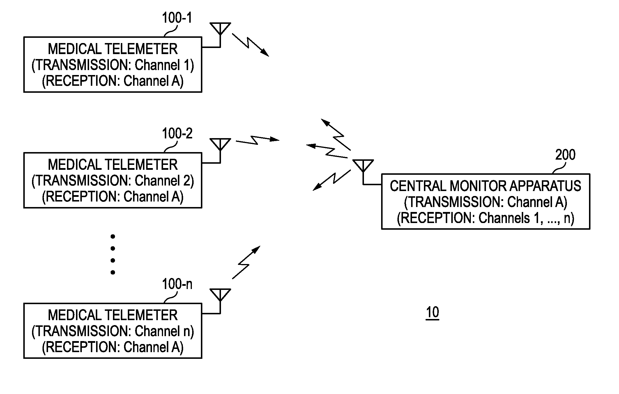
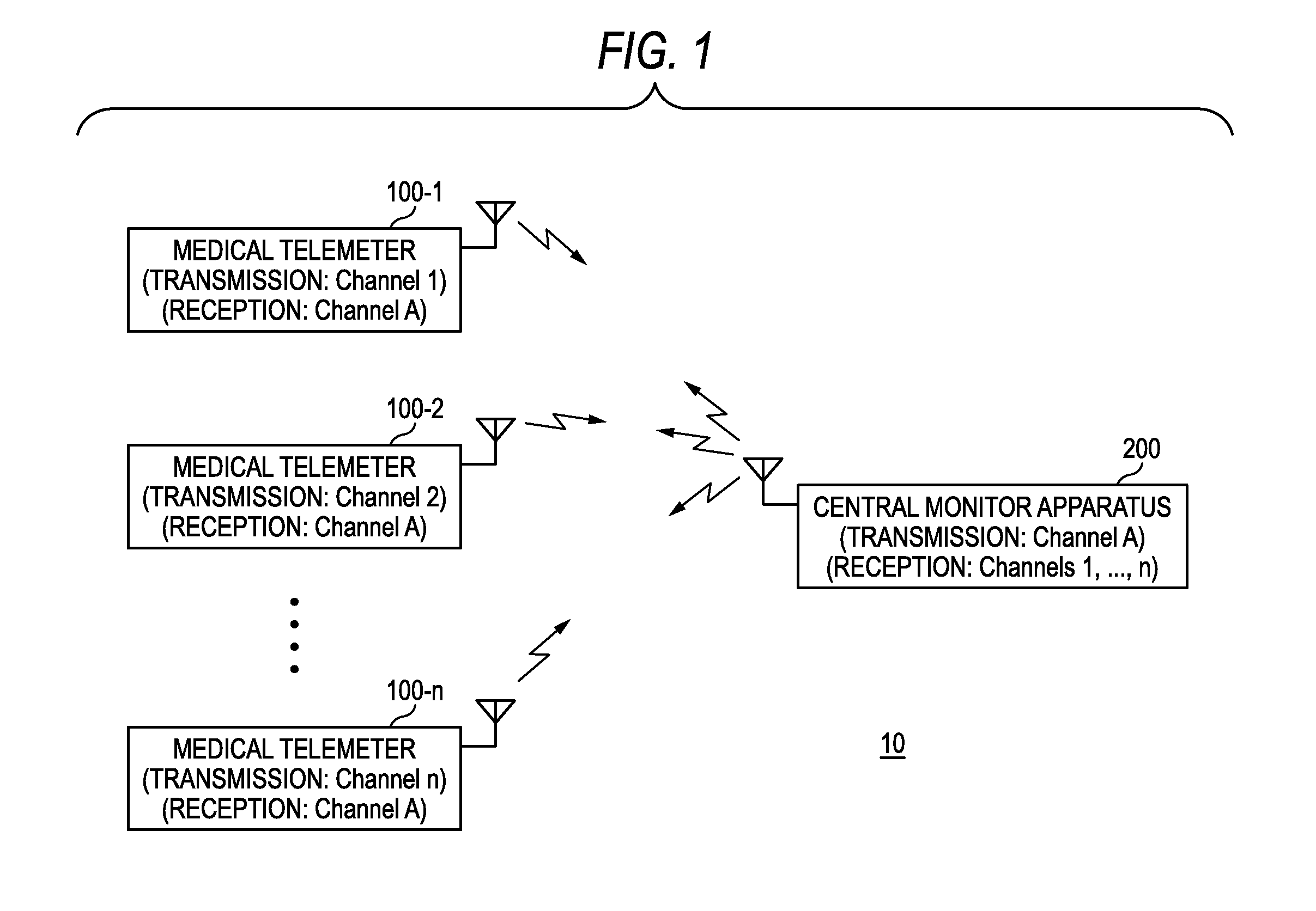
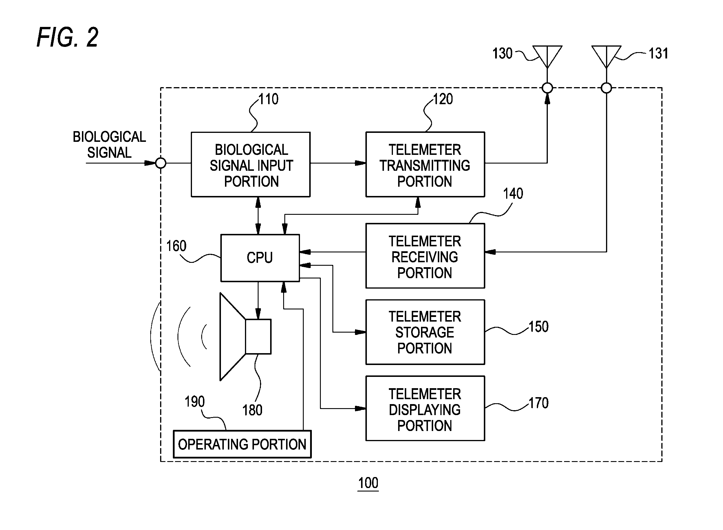
[0030]FIG. 1 is a schematic diagram of a medical telemetry system 10 of the invention. FIG. 2 is a block diagram showing a configuration example of a medical telemeter 100, and FIG. 3 is a block diagram showing a configuration example of a central monitor 200.
[0031]The medical telemetry system 10 of the embodiment includes: a plurality of medical telemeters 100 (100-1, 100-2, . . . , 100-n) each of which receives biological signals such as an electrocardiogram, respiration, blood pressure, and pulse wave of a patient from respective measuring apparatuses, which produces biological data including the received biological signals, patient information such as the name of the patient, and the like, and which transmits the biological data; and the central monitor 200 which receives the biological data transmitted from the medical telemeters 100 (100-1, 100-2, . . . , 100-n), and which displays the biological data. Hereinafter, in the case where one of the plurality of medical telemeters 1...
second embodiment
[0060]FIG. 4 is a schematic diagram of a medical telemetry system 11 of the invention. The medical telemetry system 11 of the embodiment is different from the above-described medical telemetry system 10 in that the system includes a central monitor 201 in place of the central monitor 200, and further includes an external medical apparatus 300 and a beacon repeater 400.
[0061]The external medical apparatus 300 may be a biological information measuring apparatus which can measure biological information (for example, the respiratory gas and the body temperature) of the patient, or a therapy apparatus which treats the patient, such as an artificial ventilator, or the like. In addition to a measuring portion (not shown) for measuring the biological information, the external medical apparatus 300 in the embodiment includes at least: a storage portion (not shown) for storing an identification code for identifying a specific medical telemeter 100-X (for example, the medical telemeter 100-1) ...
third embodiment
[0068]FIG. 5 is a schematic diagram of a medical telemetry system 12 of the invention. The medical telemetry system 12 of the embodiment is different from the above-described medical telemetry system 11 in that the system includes a bar code reader 500 which can read a bar code stamped on an arm band 600 attached to an arm of a patient 1000, in place of the external medical apparatus.
[0069]The bar code stamped on the arm band 600 is an example of the patient information storage portion in the invention, and indicates, for example, patient information for identifying the patient 1000 wearing the arm band 600. For example, the patient information is an ID allocated to the patient 1000, and the name and birth date of the patient 1000. The patient information is not particularly limited as far as the information identifies the patient 1000. The bar code may further indicate the identification code identifying the medical telemeter 100-X in which the patient information of the patient 10...
PUM
 Abstract
Description
Claims
Application Information
 - R&D
- Intellectual Property
- Life Sciences
- Materials
- Tech Scout
- Unparalleled Data Quality
- Higher Quality Content
- 60% Fewer Hallucinations
Browse by: Latest US Patents, China's latest patents, Technical Efficacy Thesaurus, Application Domain, Technology Topic, Popular Technical Reports.
© 2025 PatSnap. All rights reserved.Legal|Privacy policy|Modern Slavery Act Transparency Statement|Sitemap|About US| Contact US: help@patsnap.com


