

Intervertebral plate system
a technology of intervertebral plates and plates, which is applied in the field of intervertebral plate systems, can solve the problems of inability to properly protect the patient, damage to adjacent blood vessels, and pain in the back and lower extremities, and achieve the effects of reducing the risk of injury
- Summary
- Abstract
- Description
- Claims
- Application Information
AI Technical Summary
Benefits of technology
Problems solved by technology
Method used
Image

Examples
Embodiment Construction
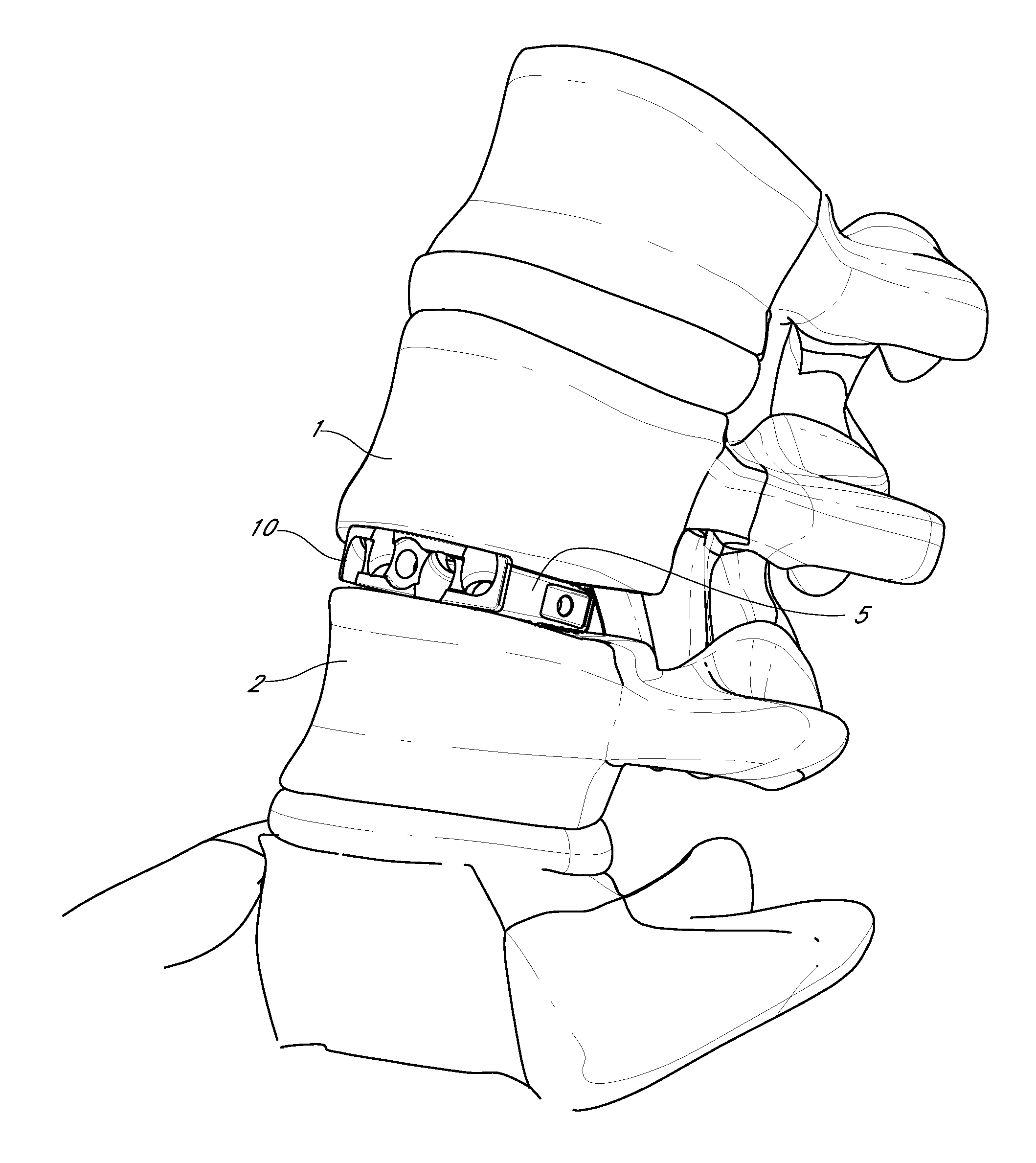
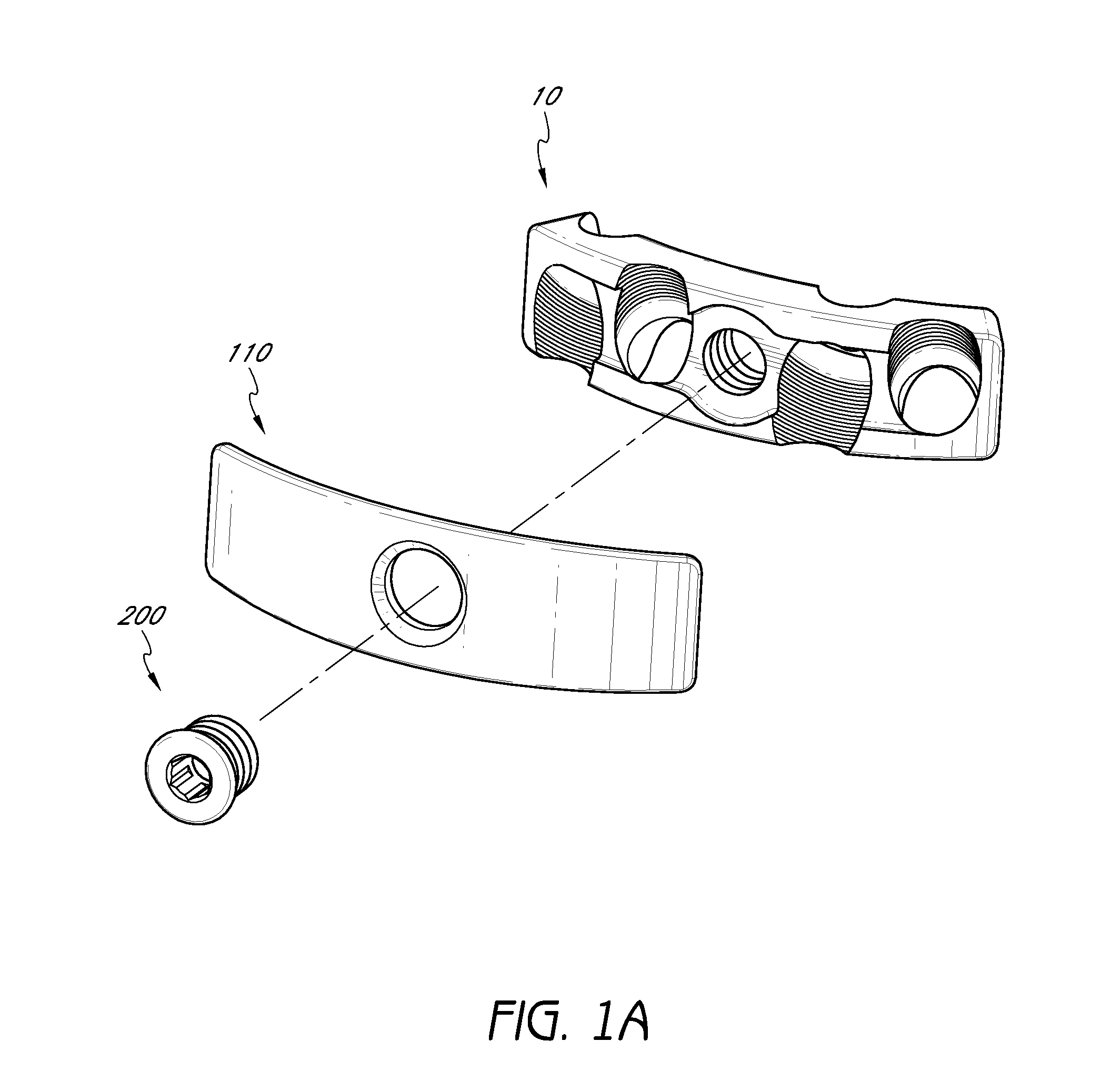
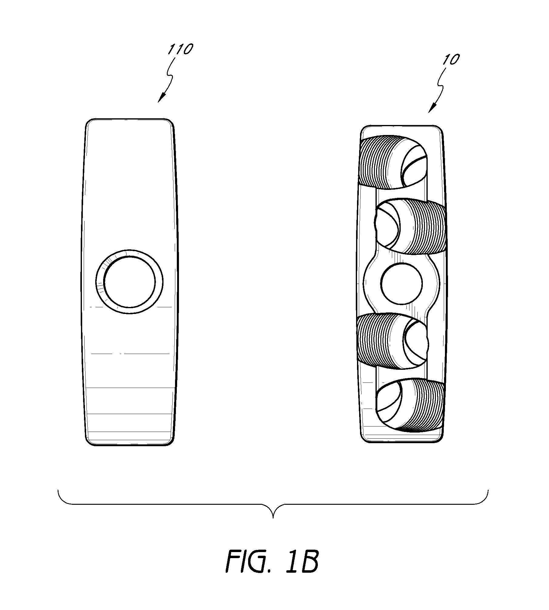
[0008]Devices and methods are provided for assisting in spinal stabilization. In some embodiments, a spinal implant system is provided. The system comprises an intervertebral spacer configured and arranged to be positioned between two vertebrae of a patient. The system further comprises a curvilinear plate configured and arranged to at least inhibit the intervertebral spacer from backing out when positioned between the two vertebrae of a patient. The curvilinear plate comprises sidewalls, a plurality of screw holes, a central screw hole for receiving a cover screw, and cover element contact surfaces. The system further comprises a plurality of bone screws adapted for insertion through the screw holes of the curvilinear plate and configured for anchoring the plate between two vertebrae of a patient. Also included in the system is a curvilinear cover element configured to inhibit the plurality of bone screws from backing out of the plate. The cover element is formed of an upper member...
PUM
 Abstract
Description
Claims
Application Information