Laterally expandable intervertebral fusion implant

a fusion implant and lateral expansion technology, applied in the field of intervertebral fusion implants, can solve the problems of large size restrictions of fusion implants, danger of collision or damage to the spinal cord, degeneration of the intervertebral disks of the vertebral column, etc., and achieve the effect of improving the support effect and small access cross section

Inactive Publication Date: 2014-07-03
FACET LINK
View PDF10 Cites 42 Cited by
  • Summary
  • Abstract
  • Description
  • Claims
  • Application Information

AI Technical Summary

Benefits of technology

[0006]The invention has set out to improve a fusion implant of the type mentioned at the outset to the extent that, while still having a small access cross section, as is conventional for minimally invasive surgery, it can nevertheless achieve an improved support effect.

Problems solved by technology

The intervertebral disks of the vertebral column suffer degeneration as a result of wear or of pathological changes.
However, this advantage is obtained at the price of a very long access route through the abdominal cavity or thoracic cavity of the patient.
Although the latter affords the advantage of a short route, there is the danger of collision with or damage to the spinal cord.
Because of the small transverse incisions used in the approach by minimally invasive surgery, the size of the fusion implants is of course greatly restricted here.
However, an inherent disadvantage of their small size is that the support function is limited because of the small dimensions and is sometimes inadequate.
Although a larger size of the fusion implants would improve the support function, this is impractical because of the limits of minimally invasive surgery.

Method used


Image

  • Laterally expandable intervertebral fusion implant
  • Laterally expandable intervertebral fusion implant
  • Laterally expandable intervertebral fusion implant

Examples


Embodiment Construction

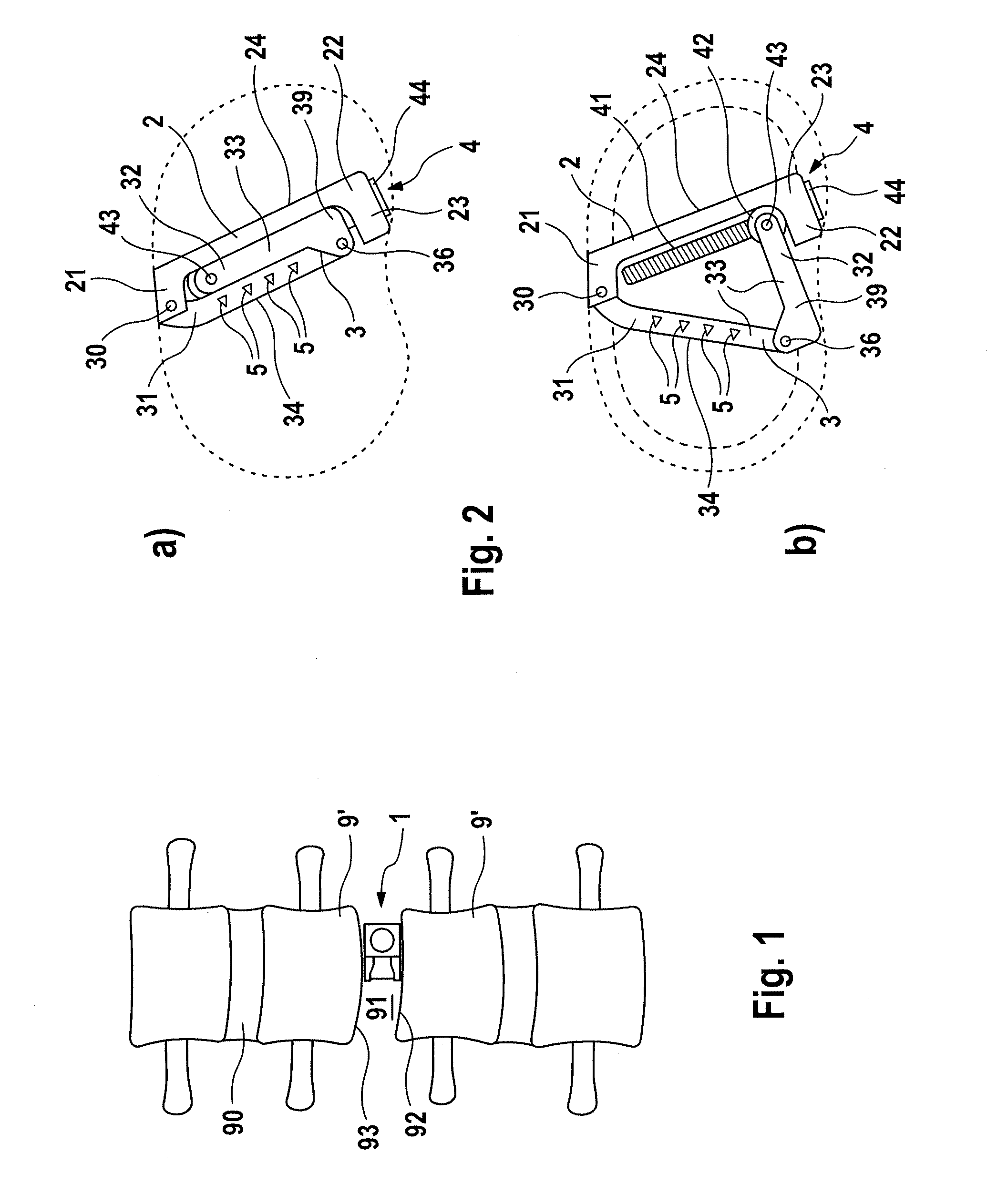
[0032]An intervertebral fusion implant, denoted by reference sign 1 in its entirety, is provided for implantation in an intervertebral space 91 between two immediately adjacent vertebral bodies 9, 9′. In a physiologically intact vertebral column, an intervertebral disk 90 is located in the intervertebral space between the vertebrae. This intervertebral disk may undergo degeneration as a result of disease or wear, with the result that it has to be at least partially resected. In order to achieve sufficient support of the intervertebral space 91, despite the loss of intervertebral disk material, and to thereby prevent collapse of the vertebral column, the intervertebral fusion implant 1 is inserted into the intervertebral space 91. It provides a supporting action and thus facilitates fusion of the two adjacent vertebrae 9, 9′ in a natural way through bone growth.

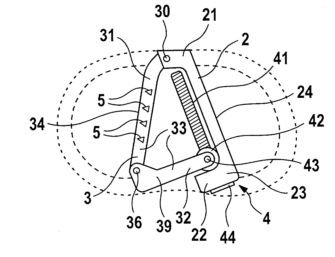
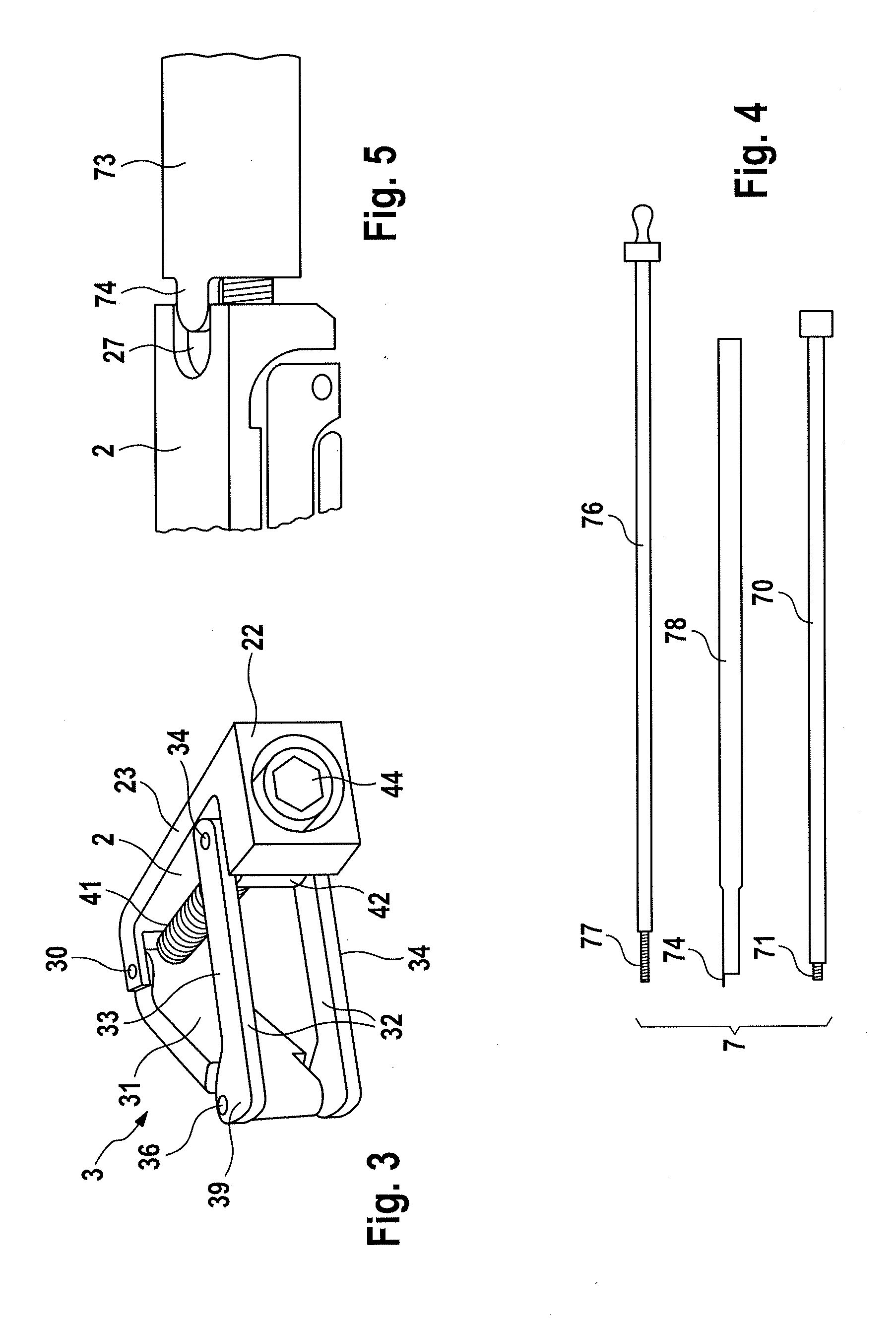
[0033]Reference is now made to the illustration in FIGS. 2 and 3. The first exemplary embodiment depicted there comprises a ...


PUM


Abstract

The invention relates to an intervertebral fusion implant for fusing two adjacent vertebrae, comprising an adjustable support body, the base surface and cover surface of which are configured to bear on end plates of the adjacent vertebrae, wherein provision is made for a side bracket, which can be pivoted laterally about a hinge and the base and cover of which have a planar design, and provision is made for an actuator for pivoting out the side bracket into a position (working position) spread from the support body. As a result, the implant has particularly small dimensions and can, after assembly at the envisaged implantation site, be actuated in such a way that it becomes larger and thereby affords a larger support surface for support in the intervertebral space. Thus, even comparatively large-area defects can be treated by minimally invasive surgery.

Description

REFERENCE TO RELATED APPLICATIONS[0001]This application is a nonprovisional of U.S. Provisional Application No. 61 / 738,278, filed Dec. 17, 2012, which claims priority to German Application No. 20 2012 011 960.5, filed Dec. 14, 2012, the entire contents of which are incorporated herein by reference.FIELD OF THE INVENTION[0002]The invention relates to an intervertebral fusion implant for fusing two adjacent vertebrae, comprising an adjustable support body, the base surface and cover surface of which are configured to bear on the vertebrae.BACKGROUND OF THE INVENTION[0003]The intervertebral disks of the vertebral column suffer degeneration as a result of wear or of pathological changes. If conservative treatment by medication and / or physiotherapy is ineffective, surgical treatment is sometimes indicated. In this connection, it is known for a movable or immovable implant to be inserted into the intervertebral space containing the degenerated intervertebral disk. This implant takes over ...

Claims


Application Information

Patent Timeline
Patent Type & Authority Applications(United States)
IPC IPC(8): A61F2/44
CPCA61F2/4455A61F2/442A61F2/447A61F2/4603A61F2/4611A61F2002/2835A61F2002/30019A61F2002/30112A61F2002/30393A61F2002/30395A61F2002/304A61F2002/30401A61F2002/30405A61F2002/30471A61F2002/30484A61F2002/30507A61F2002/3052A61F2002/3054A61F2002/30553A61F2002/30556A61F2002/30579A61F2002/30593A61F2002/30624A61F2002/30632A61F2002/30845A61F2002/3093A61F2002/4627A61F2002/4629A61F2002/4635A61F2002/4638
Inventor DMUSCHEWSKY, KLAUS
Owner FACET LINK
Why Eureka
Try Eureka