Reinforced carbon fiber/carbon foam intervertebral spine fusion device

Active Publication Date: 2012-07-19
WICHITA STATE UNIVERSITY
View PDF13 Cites 42 Cited by
  • Summary
  • Abstract
  • Description
  • Claims
  • Application Information

AI Technical Summary

Problems solved by technology

Titanium cages or PEEK spacers containing autograft or allograft bone are currently utilized to achieve this medical outcome, but are frequently unsuccessful due to a poor rate of bone growth that fails to achieve complete fusion.
Titanium cages appear to provide insufficient lordotic angle and the fused area of local bone inside cages at regions exposed to endplates is insufficient

Method used


Image

  • Reinforced carbon fiber/carbon foam intervertebral spine fusion device
  • Reinforced carbon fiber/carbon foam intervertebral spine fusion device
  • Reinforced carbon fiber/carbon foam intervertebral spine fusion device

Examples


example 1

Osteoinductive Properties of Vitreous Carbon Foam Materials

1. Materials and Methods

[0072]In this Example, 6×5 mm carbon foam discs (DUOCEL®, ERG Aerospace) prepared from bulk materials were sterilized in 70% ethanol and exhaustively rinsed in phosphate buffered saline (PBS). For BMP-2 loading studies, foam discs were submerged in PBS containing specified amounts of cytokine for 24 hours. Unbound cytokine was separated from the foam-bound fraction by low-speed centrifugation, followed by 3 rinses in PBS. The BMP-2 that was not adsorbed by the carbon foam was measured in the residual soak and subsequent wash solutions using a sandwich ELISA assay.

[0073]The rinsed discs containing adsorbed BMP-2 were then placed into wells of a tissue culture plate and C2C12 mouse myoblast cells were added to the carbon matrix by direct pipeting. Carbon materials pre-incubated in PBS containing 50, 100 or 200 ng / ml BMP-2 comprised the experimental study groups. Cell culture medium was added to the plat...

example 2

Biomaterial Analysis for Mechanical Properties

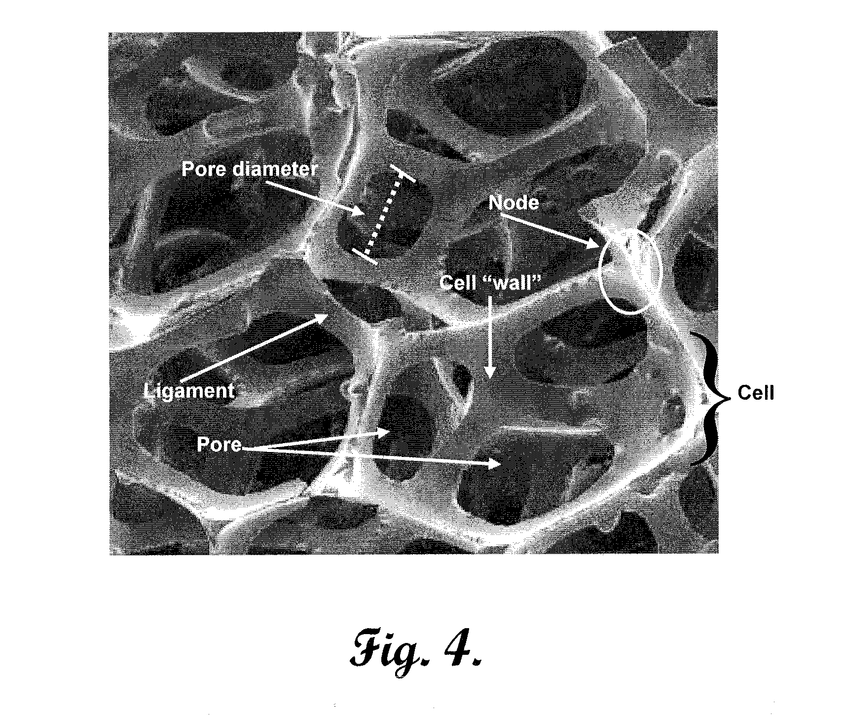
[0079]Mechanical testing of a carbon foam material DUOCEL® with a pore size of about 120 μm was performed with strict adherence to the ASTM Standard Test Method for Compressive Properties of Rigid Plastics (ASTM D-695-02a). The material was machined into cylindrical-shaped specimens with a diameter of 1 cm and thickness of 2 cm. The specimens were then tested for mechanical properties using an MTS 858 Bionix material testing system (MTS Model 858, Eden Prairie, Minn.). Load and deflection data were measured and collected by the MTS system every 0.1 seconds. Each specimen was tested in compression loading from ON to complete structural failure at a loading rate of 1.3 mm / min. The maximum stress was then determined, and the results are shown in the table below.

TABLE 1Mechanical Properties of Carbon FoamUltimateUltimateUltimateUltimateLoadStressDisplacementStrain(N)(MPa)(mm)(MPa)Average169312.570.940.026SD2401.750.410.006Max201314.911.990.0...

example 3

In Vitro Biocompatibility of Carbon Foam

1. Initial Testing

[0081]Initial biocompatibility of carbon foam was conducted using a cell culture system developed in our laboratory for the evaluation of patient hypersensitivity to orthopaedic biomaterials. Carbon in both powdered and milled fiber forms was evaluated using mononuclear cells (MNCs) obtained from 40 osteoarthritic patients under investigation for biomaterial sensitivity, along with other conventional biomaterials (polymethylmethacrylate (PMMA), Ti alloy, ultra-high-molecular-weight polyethylene (UHMWPE)). Peripheral blood was obtained from patients and MNCs were separated using Histopaque gradients. Cell suspensions of 2.5×10⁶ cells were dispensed into wells containing various concentrations of biomaterial particles. Wells with no particles (negative control) or with Concanavalin A (ConA) (positive control) were also included on the plate. Plates were incubated for 6 days. Next, 20 μl of MTT solution (5 mg / ml) were then to ea...


PUM


Abstract

An intervertebral implant for placement in the intervertebral space between two adjacent vertebral bodies is provided. The implant comprises a hollow cage and a porous core received within the cage. The cage comprises a superior surface configured to contact a first vertebral body, an inferior surface configured to contact a second vertebral body, and an outer wall extending between the superior surface and inferior surface. The outer wall comprises an exterior surface defining the outer perimeter of the implant, and an interior surface defining an inner (hollow) space or void. The porous core is received within the inner space or void, and preferably fills the void. The core comprises a carbonaceous matrix comprising a continuous phase having a surface and defining a plurality of open spaces throughout said matrix. Suitable carbonaceous matrices are selected from the group consisting of carbon foam, graphite foam, and combinations thereof. Methods of making and using the same, along with kits to facilitate such use are also provided.

Description

CROSS-REFERENCE TO RELATED APPLICATIONS[0001]The present application claims the priority benefit of U.S. Provisional Patent Application Ser. No. 61 / 433,450, filed Jan. 17, 2011, entitled Reinforced Carbon Fiber / Carbon Foam Composite Intervertebral Spine Fusion Device, incorporated by reference in its entirety herein.BACKGROUND OF THE INVENTION[0002]1. Field of the Invention[0003]The present invention relates to improved intervertebral implants for spinal fusion.[0004]2. Description of Related Art[0005]Current spine procedures for treating damaged or diseased intervertebral discs are critically dependent upon achieving interbody fusion—the replacement of the diseased disc with a spacer that allows bone growth to fuse the adjacent vertebral bodies. Titanium cages or PEEK spacers containing autograft or allograft bone are currently utilized to achieve this medical outcome, but are frequently unsuccessful due to a poor rate of bone growth that fails to achieve complete fusion. A systema...

Claims


Application Information

Patent Timeline
IPC IPC(8): A61F2/44B05D3/00B05D7/00
CPCA61F2/4465A61F2002/30843A61F2002/30677A61F2002/30772A61F2002/30795A61F2002/3092A61F2002/3093A61F2002/4475A61F2310/00161A61F2/30965A61F2002/2817A61F2002/2835A61F2002/30034A61F2002/30062A61F2002/30331A61F2002/30448A61F2002/30451A61F2002/30785A61F2002/30576A61F2002/30032A61F2002/30593A61F2/4455A61F2/44
Inventor WOOLEY, PAUL HASTINGS
Owner WICHITA STATE UNIVERSITY
Why Eureka
Try Eureka