Spinal implant with expandable fixation

a spinal implant and expandable technology, applied in the field of expandable spinal implants, can solve the problems of inability to expand and distract the endplates, inability to reliably improve the space for neural elements, and existing static cages, so as to reduce the chance of implant fixation loss, facilitate installation, and reduce the effect of pulling strength

Active Publication Date: 2015-01-13
HOWMEDICA OSTEONICS CORP
View PDF224 Cites 42 Cited by
  • Summary
  • Abstract
  • Description
  • Claims
  • Application Information

AI Technical Summary

Benefits of technology

[0004]This invention is generally directed to a spinal implant for insertion between superior and inferior vertebral end plates after partial or total removal of a spinal disc. The spinal implant embodying features of the invention is easily installed and is capable of holding the vertebral or joint sections with increased pullout strength to minimize the chance of implant fixation loss during the period when the implant is becoming incorporated into the arthrodesis bone block.

Problems solved by technology

Existing devices for interbody stabilization have important and significant limitations, including inability to expand and distract the endplates while fixing the device to prevent relative movement between the device and an adjacent vertebral body.
Moreover, current interbody spacers do not maintain interbody lordosis and can contribute to the formation of a straight or even kyphotic segment and the clinical problem of “flatback syndrome.” Separation of vertebral endplates increases space available for the neural elements, specifically the neural foramen.
Existing static cages do not reliably improve space for the neural elements.
Conventional devices for intervertebral body stabilization includes poor interface between bone and the biomaterial of the device.
That is, the ridges or coatings on the implant offer little resistance to movement applied to either side the endplates.

Method used


Image

  • Spinal implant with expandable fixation
  • Spinal implant with expandable fixation
  • Spinal implant with expandable fixation

Examples


Embodiment Construction

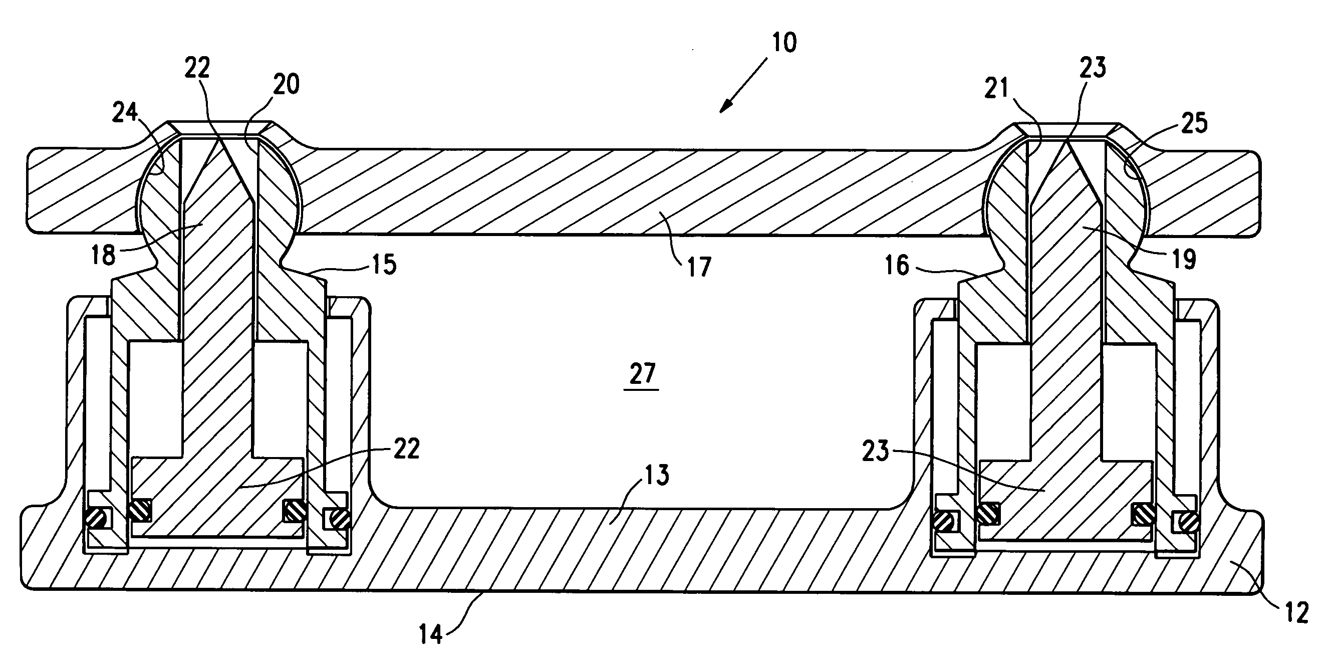
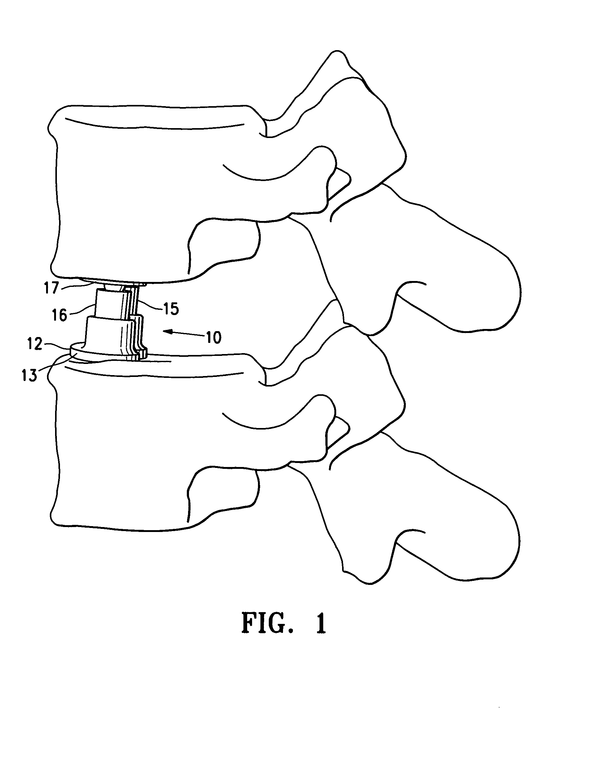
[0024]FIG. 1 illustrates location of spinal implant or SEC 10 between adjacent lumbar vertebrae in an expanded configuration. A partial or complete discectomy is performed prior to the insertion of the spinal implant 10 in a conventional manner. The SEC 10 is introduced in its unexpanded state to enable it to be inserted posteriorly with minimal trauma to the patient and risk of injury to nerve roots. Once in place the SEC 10 can be expanded to provide both medial and lateral spinal correction. The SEC has an unexpanded height of about 5 to about 15 mm, typically about 10 mm and is expandable to at least 130% to about 180% of the unexpanded height. Typically the SEC is about 9 to about 15 mm, typically about 12 mm wide and about 25 to about 40 mm, typically about 28 mm long to facilitate posterior insertion and thereby minimize trauma to the patient and risk of injury to nerve roots.

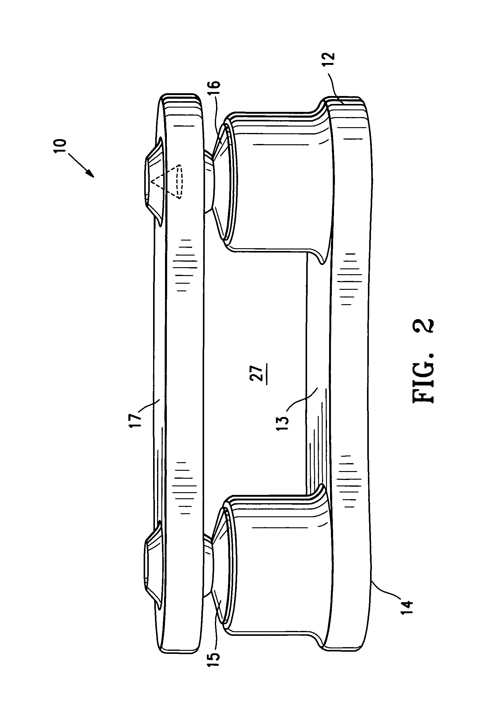
[0025]FIG. 2 illustrate the SEC 10 in a closed or unexpanded configuration and FIG. 3 illustrates the...


PUM


Abstract

A spinal implant which is configured to be deployed between adjacent vertebral bodies. The implant has at least one fixation element with a retracted configuration to facilitate deployment of the implant and an extended configuration so as to engage a surface of an adjacent vertebral body and secure the implant between two vertebral bodies. Preferably, the implant is expandable and has a minimal dimension in its unexpanded state that is smaller than the dimensions of the neuroforamen through which it must pass to be deployed within the intervertebral space. Once within the space between vertebral bodies, the implant can be expanded so as to engage the endplates of the adjacent vertebrae to effectively distract the anterior disc space, stabilize the motion segments and eliminate pathologic spine motion. Angular deformities can be corrected, and natural curvatures restored and maintained.

Description

FIELD OF THE INVENTION[0001]The invention relates to devices and methods for stabilizing the vertebral motion segment. More specifically, the field of the invention relates to an expandable spinal implant with fixation elements to fix the implant within an intervertebral space while providing controlled spinal correction in three dimensions for improved spinal intervertebral body distraction and fusion.BACKGROUND OF THE INVENTION[0002]A conventional spine cage or implant is characterized by a kidney bean shaped body which is typically inserted in tandem posteriorly through the neuroforamen of the distracted spine after a trial implant creates a pathway. Existing devices for interbody stabilization have important and significant limitations, including inability to expand and distract the endplates while fixing the device to prevent relative movement between the device and an adjacent vertebral body. Current devices for interbody stabilization include static spacers composed of titani...

Claims


Application Information

Patent Timeline
Patent Type & Authority Patents(United States)
IPC IPC(8): A61F2/44A61F2/46A61F2/28A61F2/30A61F2/48
CPCA61F2/4455A61F2/442A61F2/4611A61F2002/2835A61F2002/30378A61F2002/30505A61F2002/30538A61F2002/3055A61F2002/30556A61F2002/30579A61F2002/30583A61F2002/30601A61F2002/30841A61F2002/4666A61F2002/4693A61F2002/485A61F2210/0085A61F2220/0025A61F2220/0033A61F2250/0006A61F2250/0009A61F2310/00023A61F2/484
Inventor GROTZ, R. THOMASPRETTI, RUDY A.
Owner HOWMEDICA OSTEONICS CORP
Why Eureka
Try Eureka