Robot

Active Publication Date: 2012-03-15
SEIKO EPSON CORP
View PDF28 Cites 41 Cited by
  • Summary
  • Abstract
  • Description
  • Claims
  • Application Information

AI Technical Summary

Benefits of technology

[0008]An advantage of some aspects of the invention is to provide a robot capable of reliably gripping the object at a predetermined position without failing to catch the object.

Problems solved by technology

However, if the object is, for example, small-sized and lightweight, it becomes difficult to accurately detect the position and the posture of the object using a camera, and accurate positioning of the chuck mechanism for gripping the object is not achievable in some cases.
If the accurate positioning of the chuck mechanism is not achievable, the object and the chuck mechanism might have contact with each other at an unintended place during the gripping operation.
On that occasion, since the object is lightweight, the object moves in an unintended direction, and there arises a problem that it is not achievable to hold the object at a desired position or a problem that the object flies out of the gripping space.
If there is adopted the configuration, for example, in which the tip section and the base end section are arranged in parallel to each other in the pair of finger sections, the main body section and the mounting surface have contact with each other when gripping the object, and the tip section and the mounting surface become distant from each other to thereby make it difficult to stably grip the object.
If there is adopted a configuration, for example, in which the angle formed between the tip section and the base end section is an acute angle, there is a possibility that the tip section is shaded by the base end section when viewed from the direction in which the image of the tip section is taken by the camera, and it becomes difficult to detect the accurate gripping operation of the tip sections.

Method used


Image

  • Robot
  • Robot
  • Robot

Examples


first embodiment

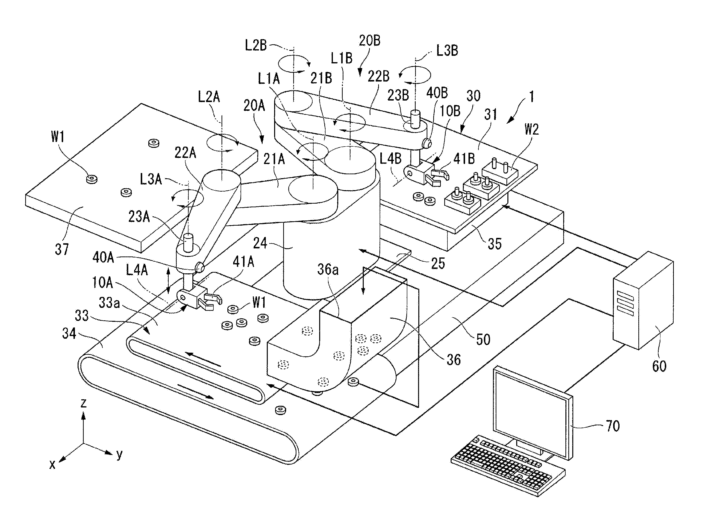
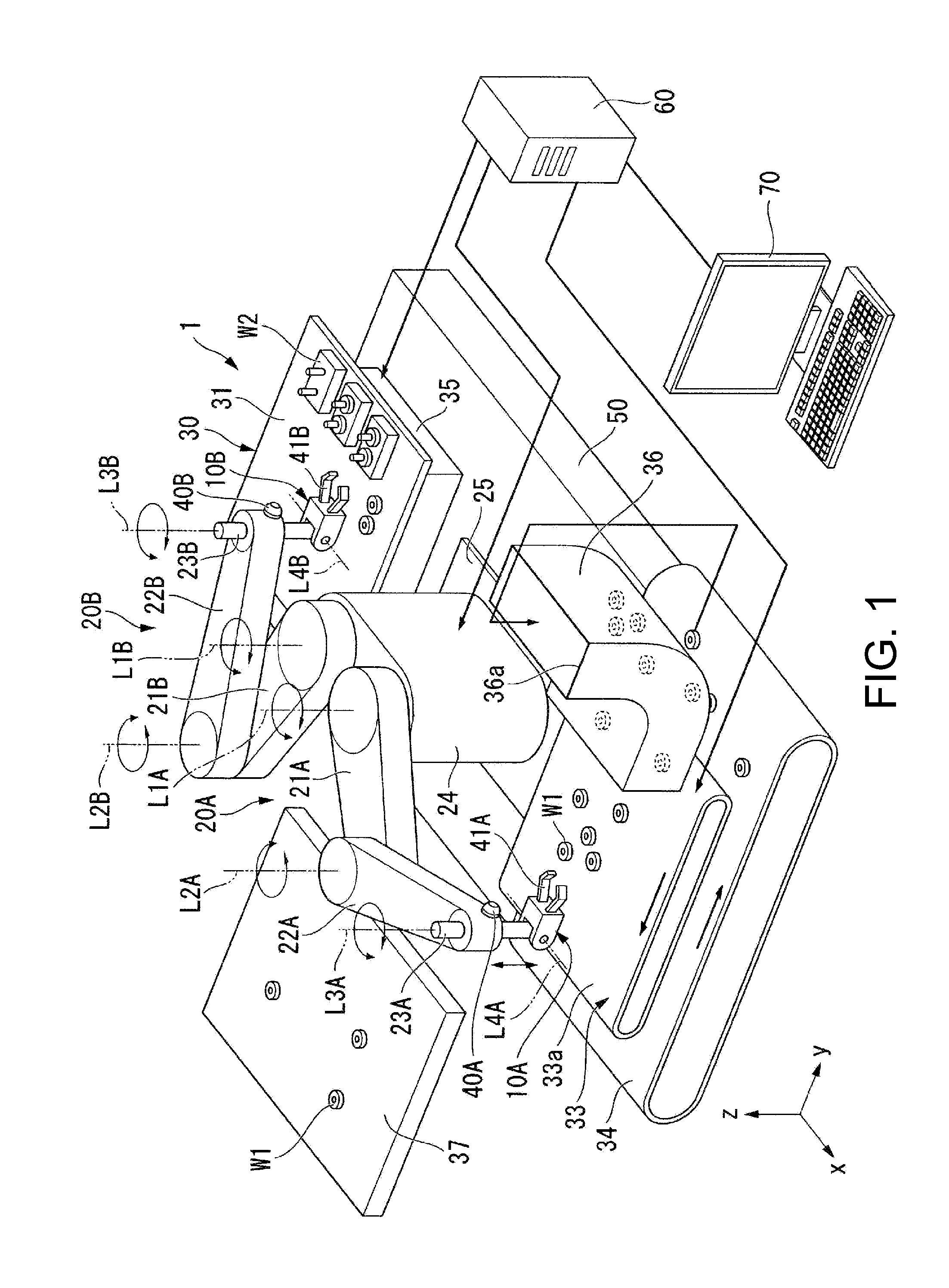
[0053]FIG. 1 is a perspective view showing a schematic configuration of a robot 1 according to a first embodiment of the invention. In FIG. 1, the reference symbol W1 denotes a first object and the reference symbol W2 denotes a second object. Further, the reference symbol L1A denotes a rotational axis of a first arm 21A, the reference symbol L2A denotes a rotational axis of a second arm 22A, the reference symbol L3A denotes a rotational axis of a third arm 23A, and the reference symbol L4A denotes a rotational axis of a gripping section 10A. The reference symbol L1B denotes a rotational axis of a first arm 21B, the reference symbol L2B denotes a rotational axis of a second arm 22B, the reference symbol L3B denotes a rotational axis of a third arm 23B, and the reference symbol L4B denotes a rotational axis of a gripping section 10B.

[0054]Here, it is assumed that the explanation will be presented exemplifying the first object W1 by a small-sized lightweight gear, and exemplifying the ...

second embodiment

[0096]FIG. 5 is a plan view corresponding to FIG. 2 and showing a configuration of a gripping section 110 according to a second embodiment of the invention. In FIG. 5, the reference symbol P11 denotes the distance between the base ends in a pair of finger sections 112, the reference symbol P12 denotes the distance between the tips of the pair of finger sections 112. The gripping section 110 of the present embodiment is different from the gripping section 10A explained in the first embodiment described above in the point that the first object W1 is gripped at three or more contact points by making the first object W1 have contact with the pair of finger sections 112 and the main body section 11. In FIG. 5, the elements substantially the same as those shown in FIG. 2 are denoted with the same reference symbols and the detailed explanation therefor will be omitted.

[0097]As shown in FIG. 5, the gripping section 110 is provided with the main body section 11 and the pair of finger section...

third embodiment

[0106]FIGS. 7A and 7B are diagrams showing a configuration of a gripping section 210 according to the third embodiment of the invention. FIG. 7A is a plan view corresponding to FIG. 2, and showing a configuration of the gripping section 210 according to the third embodiment of the invention. FIG. 7B is a cross-sectional view showing a configuration of the gripping section 210 according to the third embodiment of the invention. The gripping section 210 of the present embodiment is different from the gripping section 10A explained in the first embodiment described above in the point that a guard 212c for preventing the first object W1 from jumping out in a direction perpendicular to the mounting surface 33a is disposed on the opposite side of each of the pair of finger sections 212 to the mounting surface 33a across the first object W1. In FIGS. 7A and 7B, the elements substantially the same as those shown in FIG. 2 are denoted with the same reference symbols and the detailed explanat...


PUM


Abstract

A robot includes a gripping section adapted to grip an object by open and close a pair of finger sections, a moving device adapted to relatively move the object and the gripping section, and a control device adapted to control the moving device to move the gripping section relatively toward the object, and dispose the pair of finger sections in a periphery of the object, and then control the gripping section to open and close the pair of finger sections in a plane parallel to a mounting surface on which the object is mounted, pinch the object between the pair of finger sections from a lateral side of the object, and grip the object with the gripping section at least three contact points.

Description

BACKGROUND[0001]1. Technical Field[0002]The present invention relates to a robot.[0003]2. Related Art[0004]In the past, vertical articulated robots, horizontal articulated robots (scalar robots), Cartesian coordinate robots, and so on have been developed as industrial robots, and are selected in accordance with purposes suitable for the features thereof. In such robots, a gripping section for gripping the object is moved to a target position, and then the gripping section is made to grip the object.[0005]Such industrial robots are required to effectively grab the object, which takes a variety of unspecified postures, in a predetermined posture in working processes such as an automatic assembly process. For example, in the robot described in JP-A-2009-78312 (Document 1), it is arranged that a chuck mechanism for gripping the object can be rotated by a rotation mechanism in forward and reverse directions around the center shaft for supporting the chuck itself, and further, the rotatio...

Claims


Application Information

Patent Timeline
IPC IPC(8): B25J13/08B25J13/02B25J19/04B25J15/08
CPCB25J9/1612B25J9/043B25J15/08Y10S901/27Y10S901/50B23P19/007B25J9/0093B25J9/0096
Inventor YAMAGUCHI, YUKIHIROKOSUGE, KAZUHIROHIRATA, YASUHISAKAISUMI, AYA
Owner SEIKO EPSON CORP
Why Eureka
Try Eureka