
Planetary gear mechanism and motor-operated valve using the same

a technology of gear mechanism and gear valve, which is applied in the direction of valve operating means/release devices, machines/engines, etc., can solve the problems of deterioration of durability of gears and inability to achieve a higher reduction gear ratio, and achieve high output torque and high reduction gear ratio

Active Publication Date: 2012-03-22
FUJIKOKI CORP
View PDF15 Cites 12 Cited by
  • Summary
  • Abstract
  • Description
  • Claims
  • Application Information

AI Technical Summary

Benefits of technology

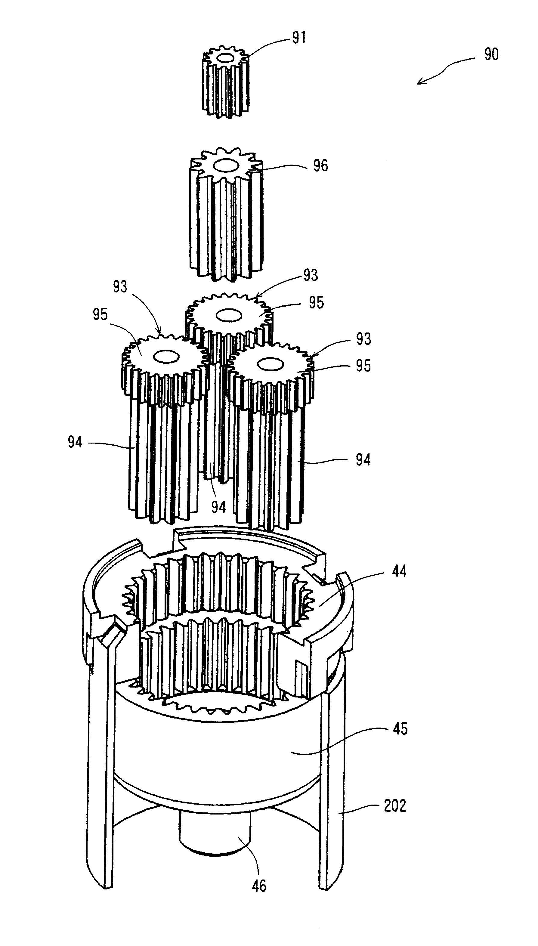
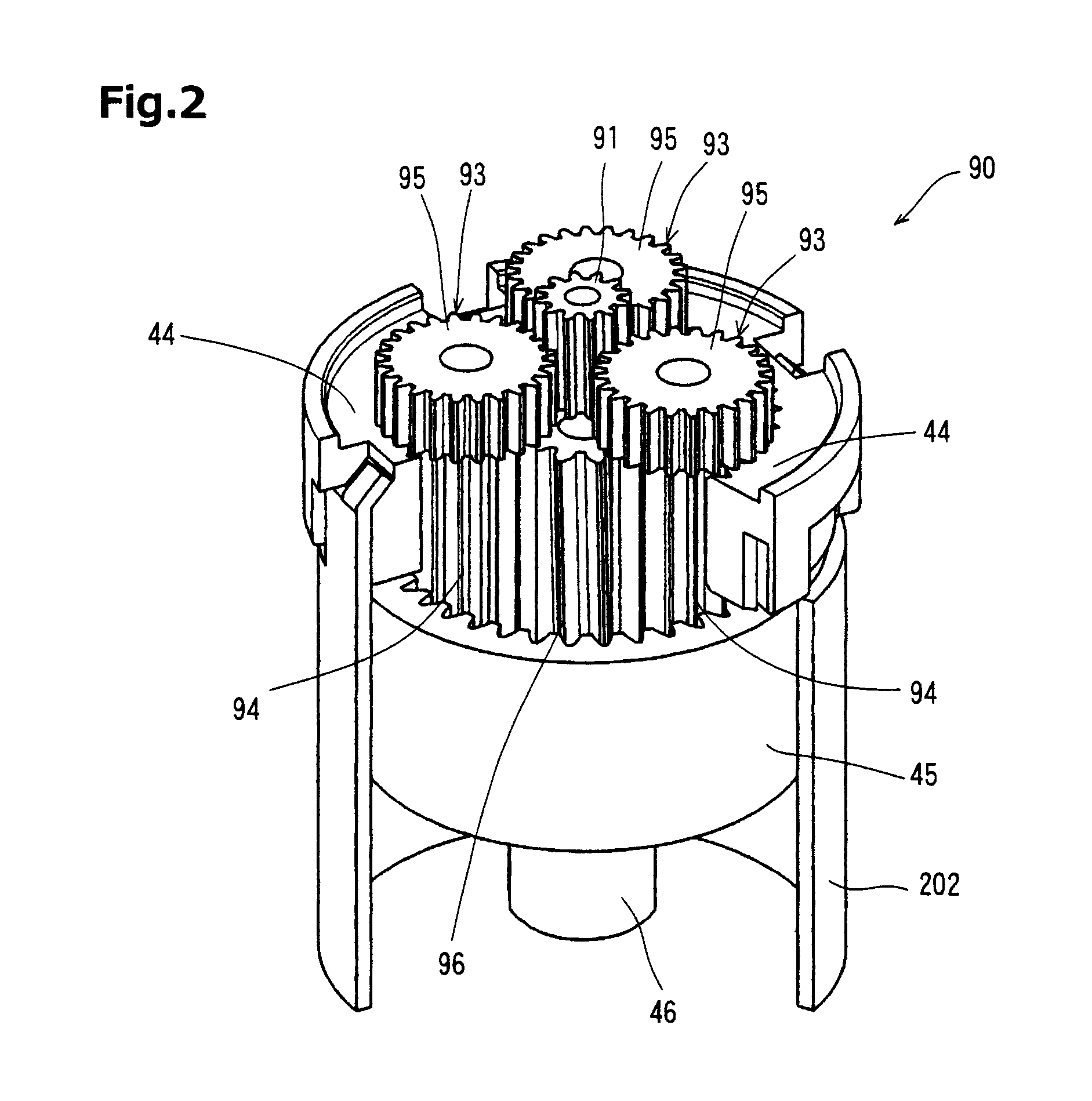
[0022]According to the present planetary gear mechanism, each planet gear is composed of a first planet gear in engagement with the internally toothed fixed gear and the internally toothed turning gear and a second planet gear in engagement with the sun gear, so that the module of the second planet gears does not have to be the same as the module of the first planet gears, and can be smaller than the module of the first planet gears.
[0023]As a result, the freedom of selection of the number of teeth of the sun gear and the second planet gear in engagement therewith can be enhanced, and thus, the reduction gear ratio of the present mechanism can be improved compared to the prior art mechanical paradox planetary gear mechanism.
[0024]Further, the driving object can be driven via a large torque by simply downsizing the module of (the sun gear and) the secondary planet gears on the input side of the drive force of the planetary gear mechanism, so that the strength and durability of the planetary gear mechanism will not be deteriorated.
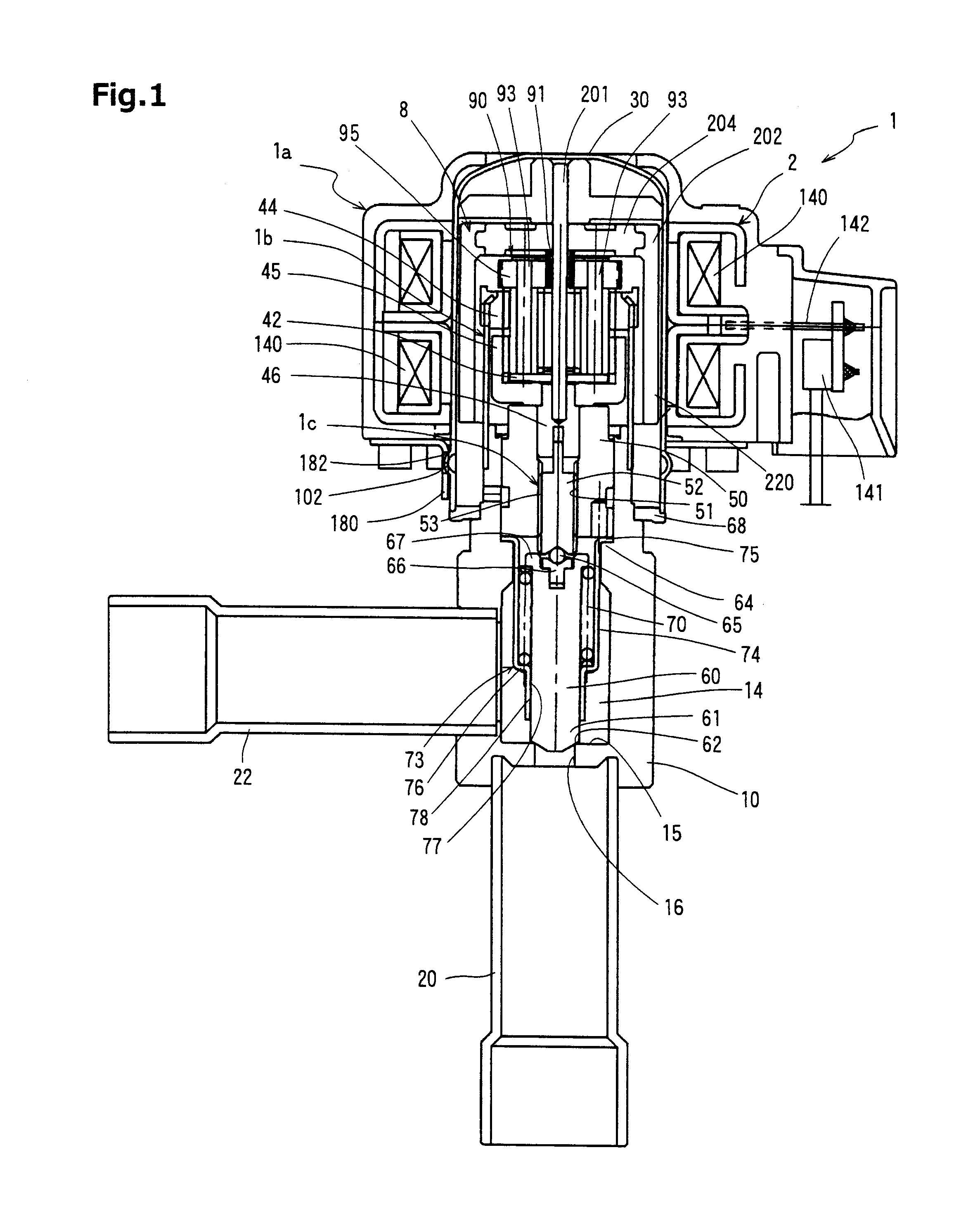
[0026]According to the motor-operated valve of the present invention, the rotation of the rotor is transmitted to the sun gear, and the rotation of the sun gear is further transmitted to one or more second planet gears having a small module and entered to the planetary gear mechanism. The rotation of the second planet gears rotates the first planet gears, each of which is formed integrally with the second planet gear. Since the first planet gears are in engagement with the internally toothed fixed gear and the internally toothed turning gear, the rotation can be output via a high reduction gear ratio based on the difference in the numbers of teeth of the two internally toothed gears. Since the internally toothed turning gear is connected to the valve member, the valve member can be driven via a high reduction gear ratio, and thereby, the present arrangement enables to achieve a high output torque for driving the valve member.
[0027]As described, the present invention adopts an arrangement in which one or more planet gears are provided, and each of which is composed of a first planet gear in engagement with the internally toothed fixed gear and the internally toothed turning gear, and a second planet gear, which is formed integrally with the first planet gear, having a smaller module than the first planet gear and further in engagement with a sun gear, so that the present planetary gear mechanism is composed of a first level of planetary gear mechanism composed of the sun gear and one or more second planet gears in engagement therewith and a second level of planetary gear mechanism composed of one or more first planet gears in engagement with the internally toothed fixed gear and the internally toothed turning gear, wherein the two levels of planet gear mechanisms are arranged in line, according to which the reduction gear ratio of the motor-operated valve can be improved further.

Problems solved by technology

However, the design of the planetary gear mechanism must satisfy various conditions (such as the number of planetary gears), and only the planetary gear mechanisms designed to satisfy such conditions can be manufactured.
According to the above-described planetary gear mechanism, the reduction gear ratio is set within a certain range when the external dimensions of the fixed gear and the output gear are determined, and it is impossible to achieve a higher reduction gear ratio.
If the module is downsized in order to prevent the increase in size of the gear mechanism, the durability of the gears is deteriorated.

Method used


Image

  • Planetary gear mechanism and motor-operated valve using the same
  • Planetary gear mechanism and motor-operated valve using the same
  • Planetary gear mechanism and motor-operated valve using the same

Examples


Embodiment Construction

[0034]Now, a preferred embodiment of the planetary gear mechanism according to the present invention will be described with reference to the accompanied drawings. In the description of the embodiment of the planetary gear mechanism 90 and the motor-operated valve 1 according to the present invention illustrated in FIGS. 1 through 3, the components or parts which are the same as or equivalent to those constituting the prior art planetary gear mechanism 40 and prior art motor-operated valve 100 illustrated in FIGS. 4 through 6 are denoted with the same reference numbers, and detailed descriptions thereof are omitted.

[0035]According to the embodiment illustrated in FIGS. 1 through 3, a sun gear 91 either fixed to or integrated with the sun gear member 204 is designed as a gear having a smaller pitch diameter than the sun gear 41 of the prior art planetary gear mechanism shown in FIGS. 4 through 6 but having the same number of teeth. In other words, the sun gear 91 according to the pres...


PUM


Abstract

The invention provides a planetary gear mechanism achieving a greater reduction gear ratio without increasing the number of teeth of the gears, thereby enabling downsizing. In a planetary gear mechanism 1, a sun gear 91 functioning as an input gear receives smaller load than an internally toothed output gear 45, so gears (second planet gears 95) having a smaller module are connected to the planet gears 93, and the sun gear 91 is in engagement with the second planet gears 95. The sun gear 91 is formed of a same module as the second planet gears 95. The rotation of the sun gear 91 is reduced in speed and transmitted to the second planet gears 95, and rotation of the second planet gears 95 rotated at a reduced speed is further reduced by the slight difference in the numbers of teeth of the ring gear 44 and the internally toothed output gear 45 before being output.

Description

[0001]The present application is based on and claims priority of Japanese patent application No. 2010-212642 filed on Sep. 22, 2010, the entire contents of which are hereby incorporated by reference.BACKGROUND OF THE INVENTION[0002]1. Field of the Invention[0003]The present invention relates to a planetary gear mechanism comprising a sun gear, one or more planet gears, an internally toothed fixed gear and an internally toothed turning gear, and a motor-operated valve using the same for controlling the flow rate of a refrigerant in an air conditioner or the like.[0004]2. Description of the Related Art[0005]Conventionally, so-called motor-operated valves exist for controlling the opening and closing of valves via electric motors in which the rotation of a rotor is directly transmitted to a screw mechanism to control the opening and closing of valves. There are also proposed motor-operated valves in which the rotation of the rotor is reduced via a reduction gear mechanism before the ro...

Claims


Application Information

Patent Timeline
Patent Type & Authority Applications(United States)
IPC IPC(8): F16K31/53F16H57/08
CPCF01L1/352F16H1/46F01L2820/032
Inventor ARAI, YUSUKE
Owner FUJIKOKI CORP
Learn More