Motor Drive Circuit and Illumination Apparatus

a technology of motor drive and illumination apparatus, which is applied in the direction of motor/generator/converter stopper, dynamo-electric converter control, instruments, etc., can solve the problems of reduced efficiency and life, low heat generation

Inactive Publication Date: 2012-03-22
SEMICON COMPONENTS IND LLC
View PDF11 Cites 7 Cited by
  • Summary
  • Abstract
  • Description
  • Claims
  • Application Information

AI Technical Summary

Benefits of technology

[0010]A motor drive circuit according to an aspect of the present invention, includes: an output transistor configured to supply a drive current to a drive coil of a motor configured to cause a fan to rotate so as to blow air to cool an object to be cooled; a switching control circuit configured to control switching of the output transistor so that the motor rotates in a first direction to cool the object to be cooled, or rotates in a second direction opposite to the first direction; and a switching circuit configured to, when

Problems solved by technology

On the other hand, the LED has lower heat generation than that of the incandescent lamp but is susceptible to h

Method used


Image

  • Motor Drive Circuit and Illumination Apparatus
  • Motor Drive Circuit and Illumination Apparatus
  • Motor Drive Circuit and Illumination Apparatus

Examples


Embodiment Construction

[0020]At least the following details will become apparent from descriptions of this specification and of the accompanying drawings.

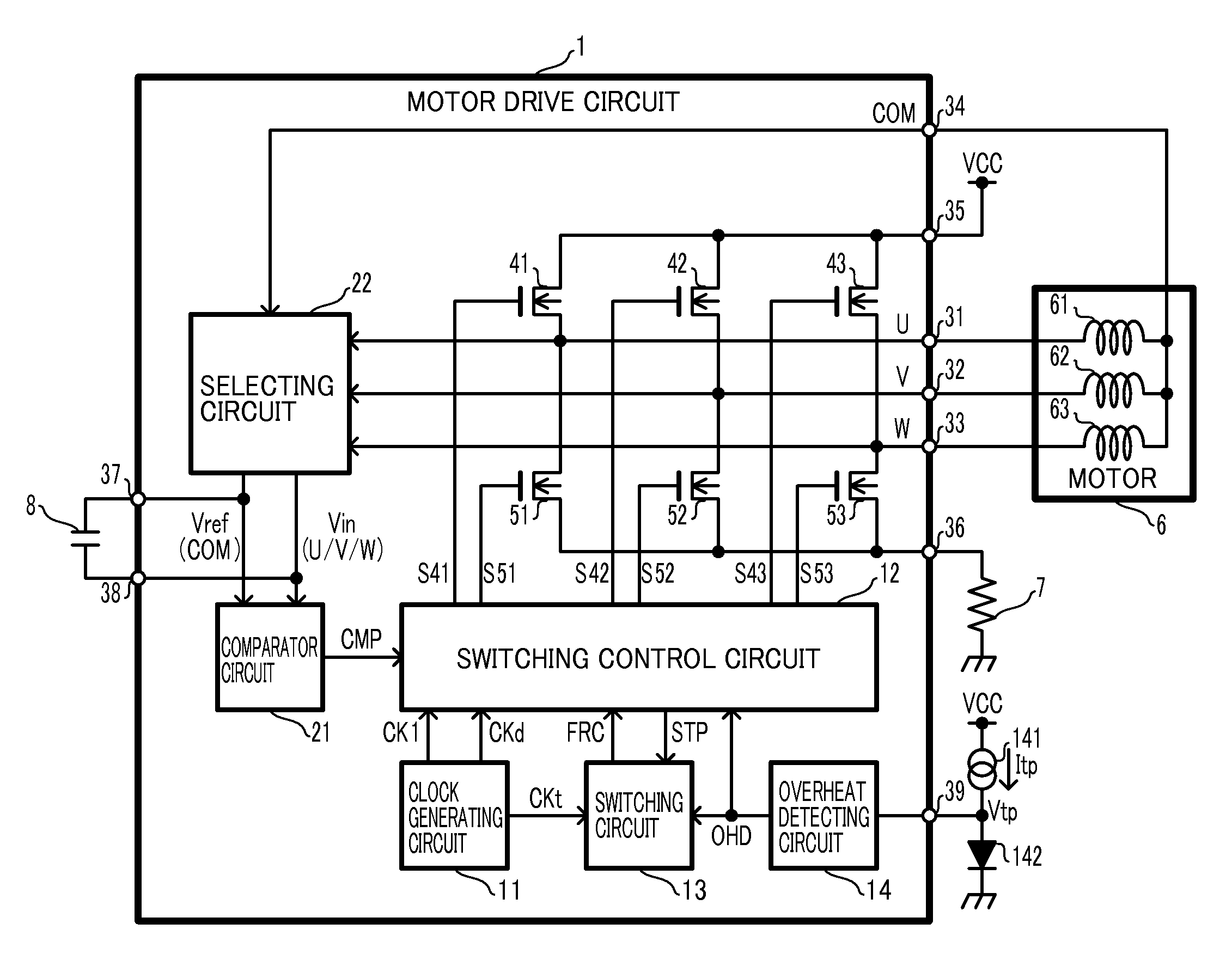
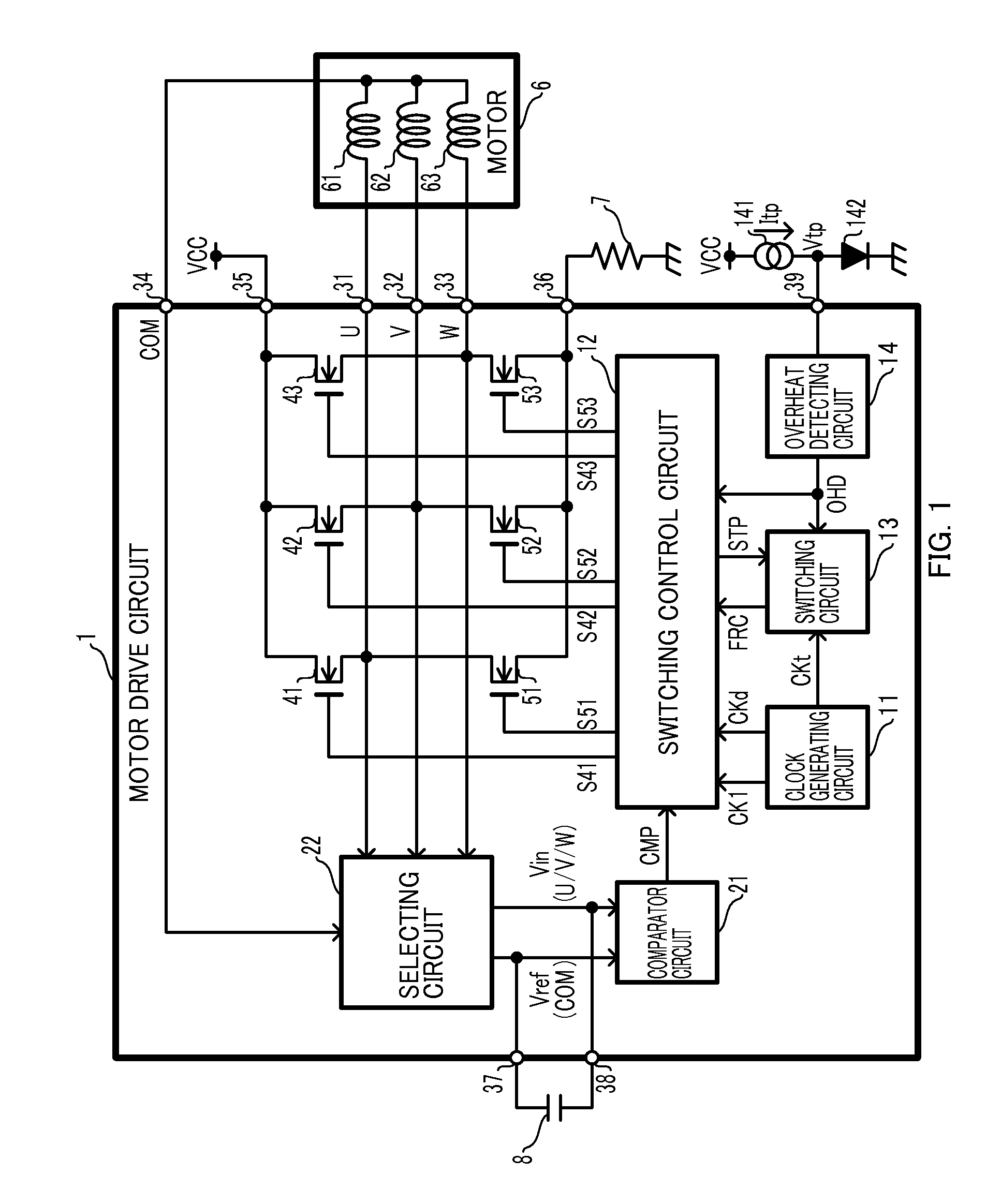
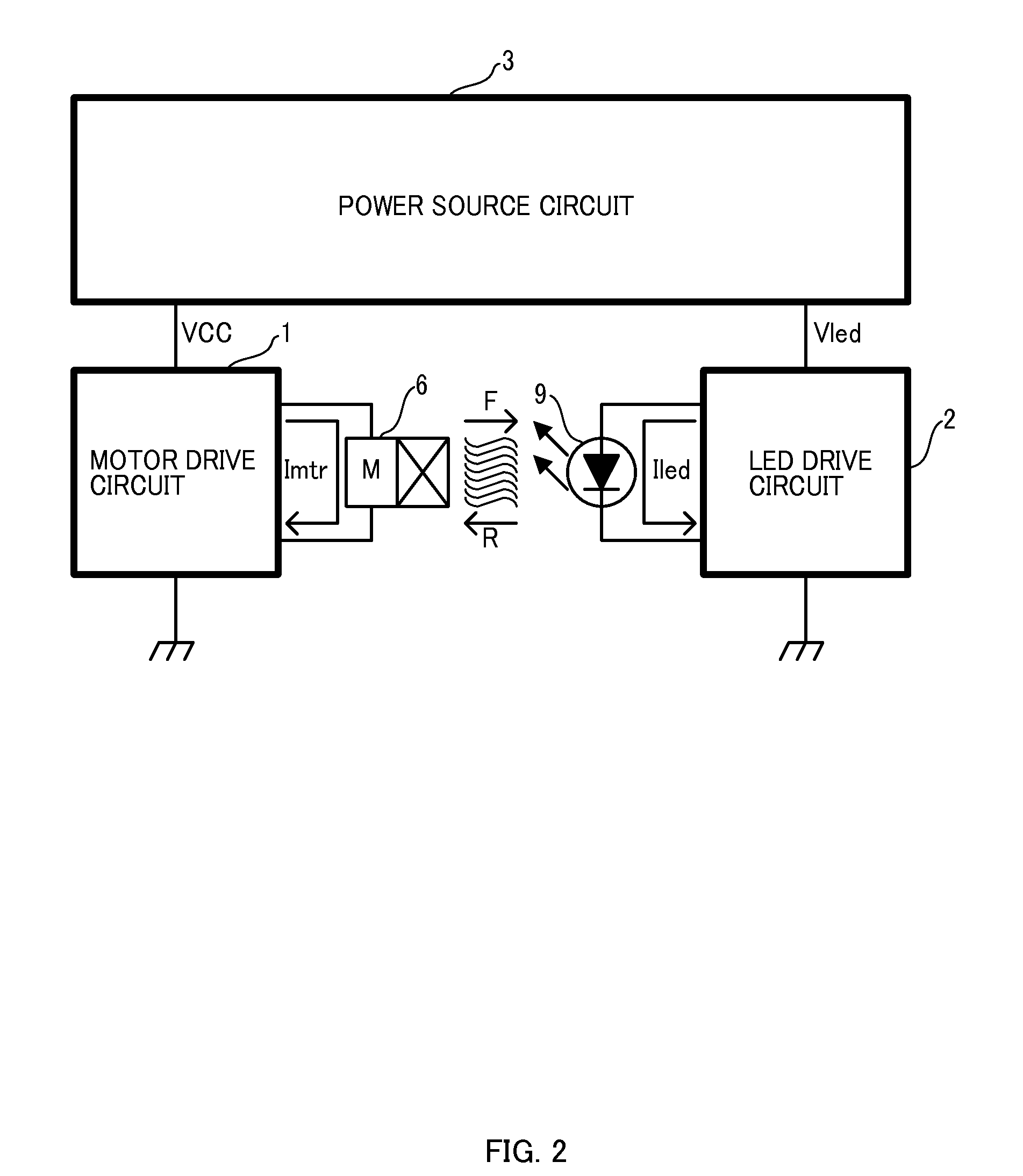
[0021]An outline will hereinafter be described of a configuration of an illumination apparatus as a whole including a motor drive circuit according to an embodiment of the present invention, which will be described later, with reference to FIG. 2. Detailed description will be given later of a configuration of a motor drive circuit 1.

[0022]The illumination apparatus shown in FIG. 2 is an illumination apparatus employing an LED as an illumination element, and includes the motor drive circuit 1, an LED drive circuit 2, a power supply circuit 3, a motor 6, and an LED 9. The motor drive circuit 1 and the LED drive circuit 2 are connected to the power supply circuit 3. Further, the motor 6 is connected to the motor drive circuit 1 and the LED 9 is connected to the LED drive circuit 2. It is assumed that the rotating shaft of the motor 6 is connected to a fan, ...


PUM


Abstract

A motor-drive circuit includes: an output transistor configured to supply a drive current to a motor for a cooling fan; a switching-control circuit configured to control switching of the output transistor so that the motor rotates in a first direction, or rotates in a second direction opposite to the first direction; and a switching circuit configured to, when a first time has elapsed since start of rotation of the motor in the first direction, cause the switching-control circuit to start switching control so that the motor stops rotating in the first direction and thereafter rotates in the second direction, and configured to, when a second time has elapsed since start of rotation of the motor in the second direction, cause the switching-control circuit to start switching control so that the motor stops rotating in the second direction and thereafter rotates in the first direction.

Description

CROSS-REFERENCE TO RELATED APPLICATION[0001]This application claims the benefit of priority to Japanese Patent Application No. 2010-068644, filed Mar. 24, 2010, of which full contents are incorporated herein by reference.BACKGROUND OF THE INVENTION[0002]1. Field of the Invention[0003]The present invention relates to a motor drive and an illumination apparatus circuit[0004]2. Description of the Related Art[0005]Recently, an LED (Light Emitting Diode) is used for an illuminating purpose as well. In particular, since the[0006]LED has a longer life as compared with an incandescent bulb, it is suitable for being used in an illumination apparatus to be installed in a place inconvenient for replacement such as a ceiling. On the other hand, the LED has lower heat generation than that of the incandescent lamp but is susceptible to heat, thereby requiring appropriate cooling using a heat sink, etc., to prevent reduction in efficiency and life.[0007]For example, Japanese Patent Laid-Open Publi...

Claims


Application Information

Patent Timeline
IPC IPC(8): H01J7/24H02P7/29H02P6/22H02P6/06H02P6/08
CPCH02P6/22H02P6/003H02P6/30
Inventor YOSHITOMI, TETSUYATANABE, MASASHISUZUKI, SYUNJI
Owner SEMICON COMPONENTS IND LLC
Why Eureka
Try Eureka