
Device for controlling current of LED

a technology of led modules and current control, which is applied in the direction of electric variable regulation, process and machine control, instruments, etc., can solve the problems of difficult standardization of led modules, noise included in voltage output, and difficulty in standardizing led modules

Active Publication Date: 2012-03-22
SKAICHIPS CO LTD
View PDF3 Cites 6 Cited by
  • Summary
  • Abstract
  • Description
  • Claims
  • Application Information

AI Technical Summary

Benefits of technology

[0012]An object of the present invention is to provide a device for changing current of an LED without separately adding a digital block or separately changing a resistor by adjusting current supplied to a current amplifier using a SEL input without an effect of a noise.

Problems solved by technology

When voltage is applied from the outside, a noise included in the voltage appears in output current as it is.
However, even in the case of using the scheme of changing the external resistor as described above, since a resistor of each of the LED modules should be changed, it is difficult to standardize the LED modules.
However, as described above, when the ADIM voltage is input from the outside, an input noise may be reflected on an output as it is, and when the RLED is changed, it is difficult to standardize the LED module.
However, in the case of using the digital block, a separate digital source for generating a complicated digital clock signal is required.

Method used


Image

  • Device for controlling current of LED
  • Device for controlling current of LED
  • Device for controlling current of LED

Examples


Embodiment Construction

[0024]Hereinafter, configuration and operation of the present invention will be described in more detail with reference to the accompanying drawings.

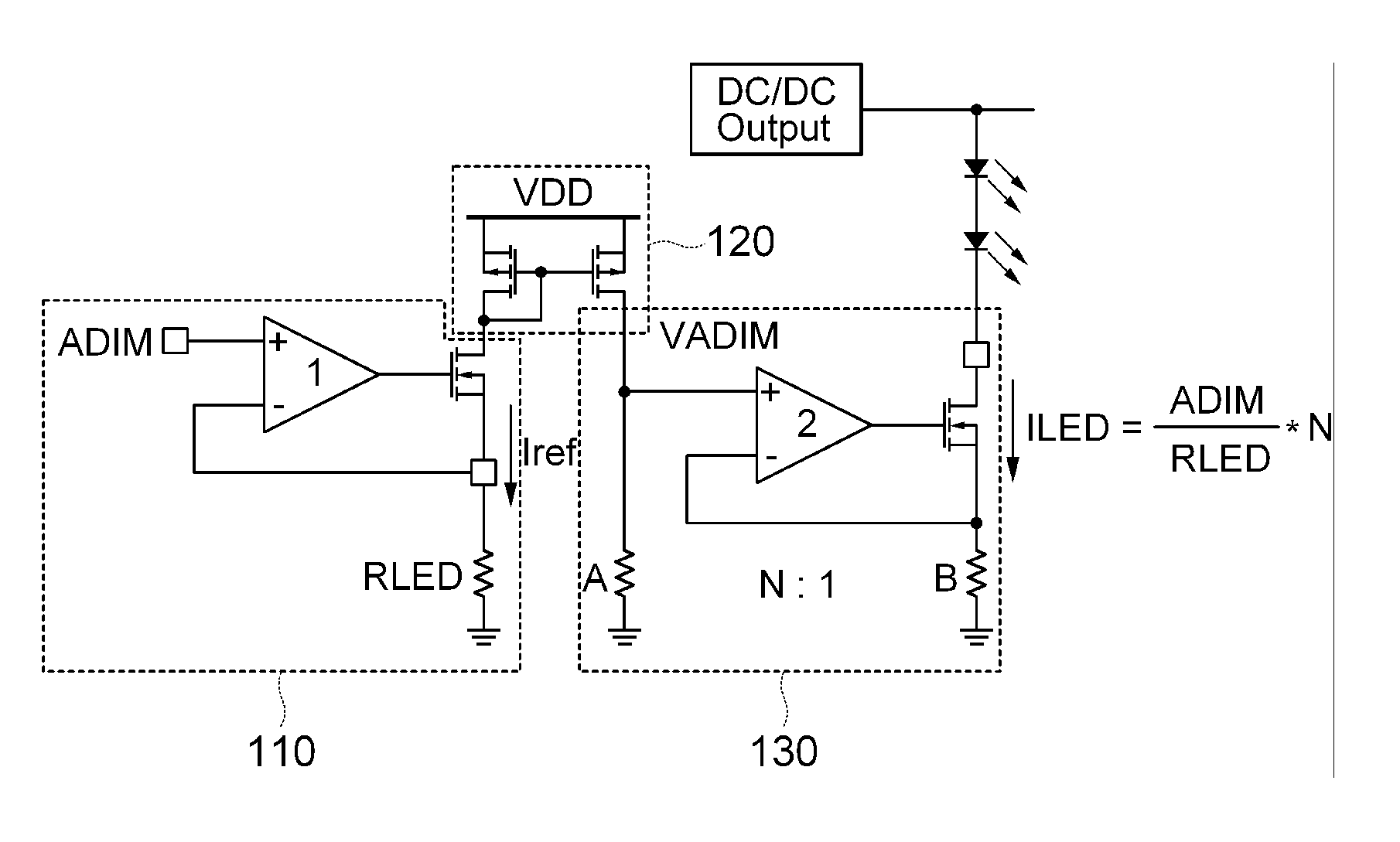
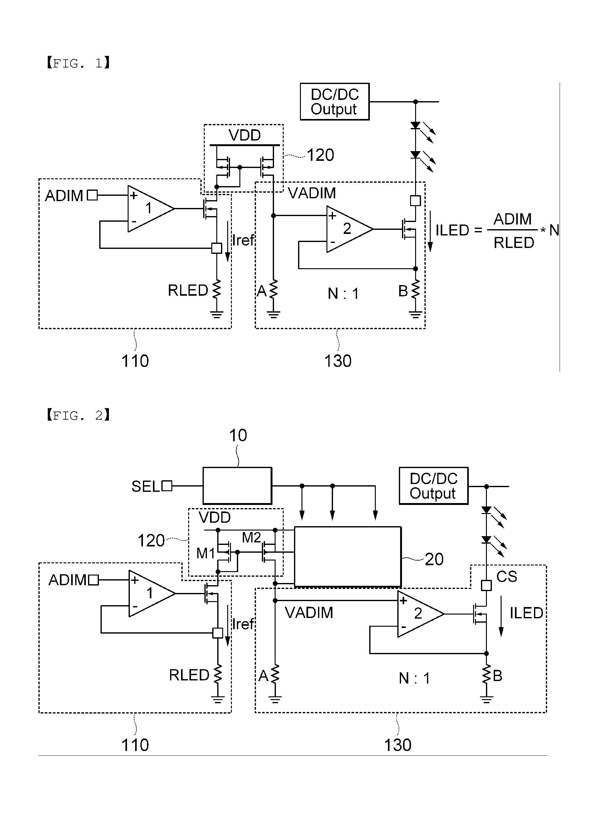
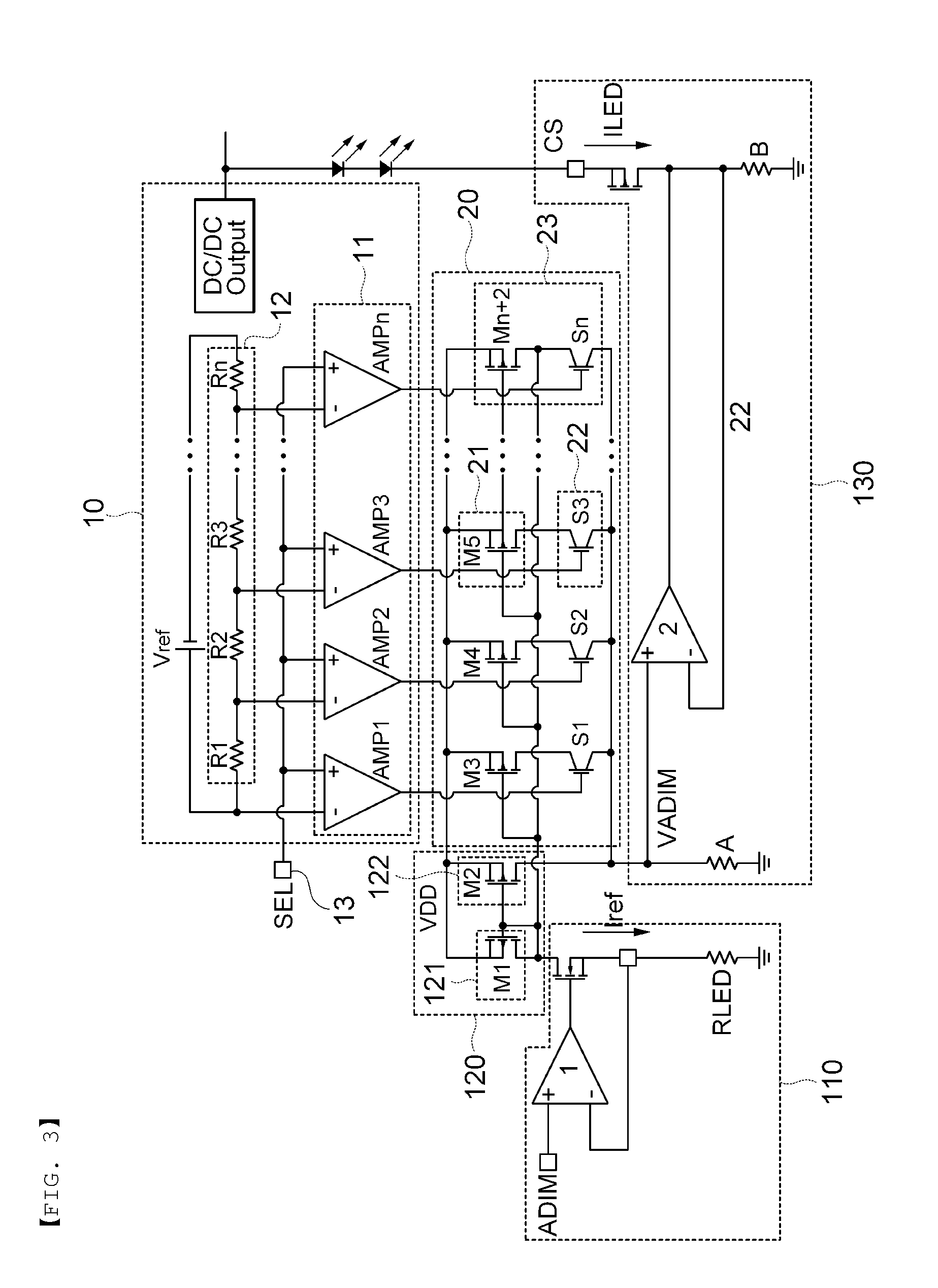
[0025]FIG. 2 is a circuit diagram showing a configuration according to an exemplary embodiment of the present invention. A configuration in which a selector 10 and a current changing unit 20 are further included in the LED driving circuit according to the related art including the constant current generator 110, the current mirror 120 and the current amplifier 130 is shown in FIG. 2.

[0026]At this time, the specific configuration of the constant current generator 110, the current mirror 120 and the current amplifier 130 is similar to that widely used in the related art. Therefore, the detailed description thereof will be omitted.

[0027]Meanwhile, the selector 10 generates an output signal according to a signal (SEL signal) input to a control signal input terminal 13 to control the current changing unit 20. The current changing unit 20 cha...


PUM


Abstract

Disclosed herein is a device for controlling current of an LED including a constant current generator, a current mirror, and a current amplifier, the device controlling current of an LED, comprising: a selector outputting an L signal or an H signal according to an input control signal; and a current changing unit formed by connecting at least one switching unit in parallel, the switching unit including a transistor and a switch connected to the transistor in series. The device for controlling current of an LED adjusts current supplied to the current amplifier using a SEL input without an effect of a noise, thereby making it possible to change the current of the LED without separately changing a resistor.

Description

CROSS REFERENCE(S) TO RELATED APPLICATIONS[0001]This application claims the benefit under 35 U.S.C. Section [120, 119, 119(e)] of Korean Patent Application Serial No. 10-2010-0090997, entitled “Device for Controlling Current of LED” filed on Sep. 16, 2010, which is hereby incorporated by reference in its entirety into this application.BACKGROUND OF THE INVENTION[0002]1. Technical Field[0003]The present invention relates to a device for controlling current of a light emitting diode (LED), and more particularly, to a device for changing current of an LED capable of changing current determining brightness of the LED without separately changing an external power supply or a resistor.[0004]2. Description of the Related Art[0005]An organic light emitting diode (LED) has been widely used in various fields such as illumination, a backlight unit (BLU), or the like. Recently, as a market for the LED has rapidly expanded, the related technologies have rapidly advanced correspondingly.[0006]Mea...

Claims


Application Information

Patent Timeline
IPC IPC(8): H05B37/02
CPCH05B33/0815Y02B20/347H05B33/0824H05B45/44Y02B20/30H05B45/3725
Inventor SUNG, JOON YOUPLEE, JAE SHINKONG, SEUNG KONKWON, JUNG SUNKIM, JUNG HYUNHWANG, BO HYUN
Owner SKAICHIPS CO LTD
Learn More