Apparatus and method for determining a touch input

a technology of touch input and apparatus, applied in the direction of resistance/reactance/impedence, instruments, pulse techniques, etc., can solve the problems of not accurately registering desired touches, unable to accurately register touch input, and being susceptible to nois

Active Publication Date: 2012-03-22
ALSENTIS
View PDF8 Cites 59 Cited by
  • Summary
  • Abstract
  • Description
  • Claims
  • Application Information

AI Technical Summary

Problems solved by technology

If the surface is “too sensitive,” it may be susceptible to noise, or it may register false touches.
If the surface is “too insensitive,” it may not accurately register desired touches, or fail to register a touch altogether.
Problems with the aforementioned method include: (1) inability to compensate for dielectric variations among different objects; (2) susceptibility to environmental conditions; (3) inability to compensate for manufacturing tolerances and variations in component materials; and (4) when configured as a touch sensor, inability to detect an input at the touch surface without respect to whether a finger is gloved or not.
However, the determination of an averaged or compensated reference value often requires processing in software or a devoted microcontroller, which in turn can add cost and unneeded complexity to the overall system.
Even with averaging algorithms, some variation, such as increased touch substrate thickness, can not be adequately compensated for to eliminate sensitivity variations.
However, the determination of a compensated reference value can be costly and impractical, requiring processing in software or a devoted microcontroller, and potentially delaying the response time of the associated capacitive sensor, and ultimately may not be able overcome sensitivity variations or detect valid stimuli such as a gloved or ungloved finger when the capacitive sensor is configured as a touch sensor.

Method used


Image

  • Apparatus and method for determining a touch input
  • Apparatus and method for determining a touch input
  • Apparatus and method for determining a touch input

Examples


Embodiment Construction

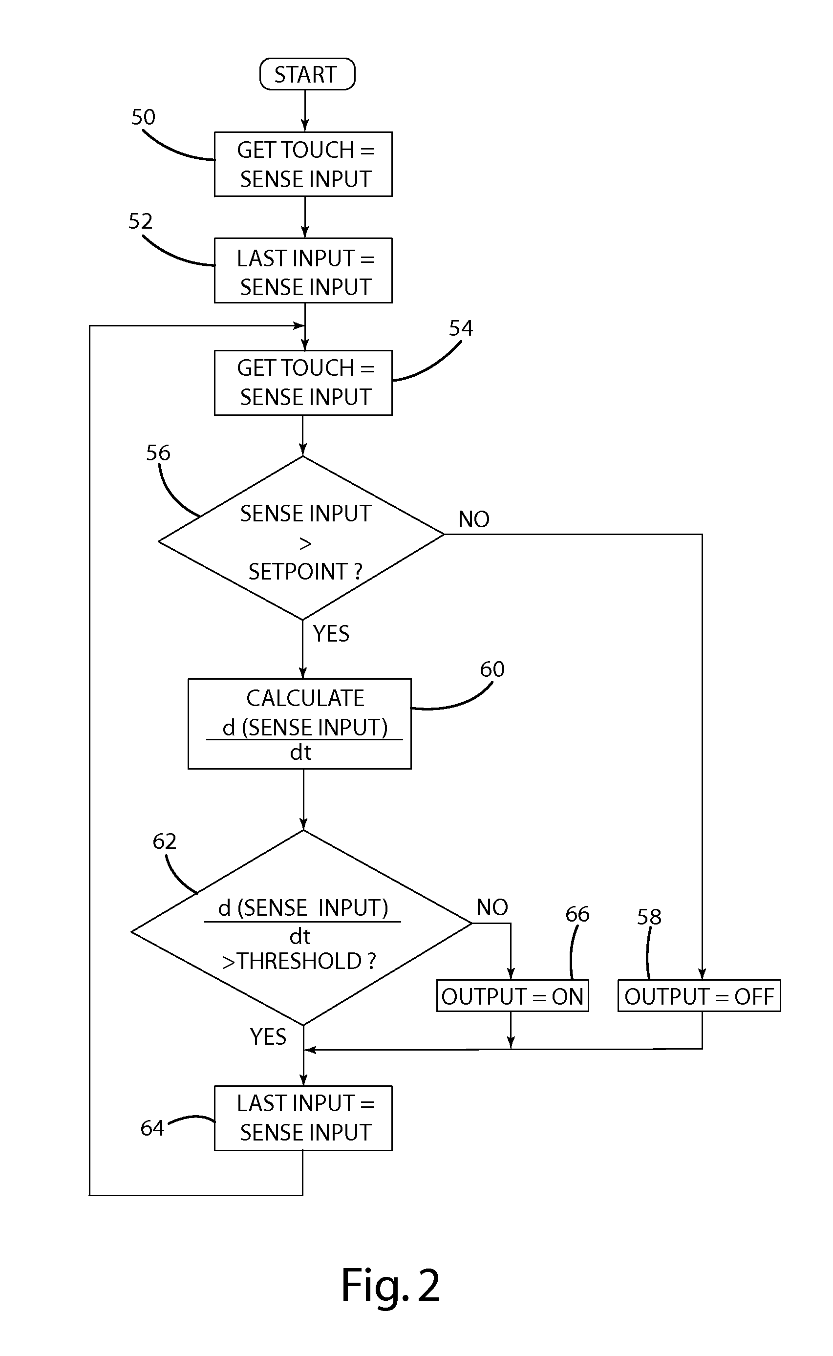
[0025]The invention as contemplated and disclosed herein can greatly improve the performance of capacitive sensors over known capacitive sensing systems and methods. In particular, the system and method set forth below utilizes the rate of change of a capacitive sensor output, the absolute value of which remains positive as an object approaches the capacitive sensor from some distance away, and which rapidly declines as the object comes to rest relative to the capacitive sensor.

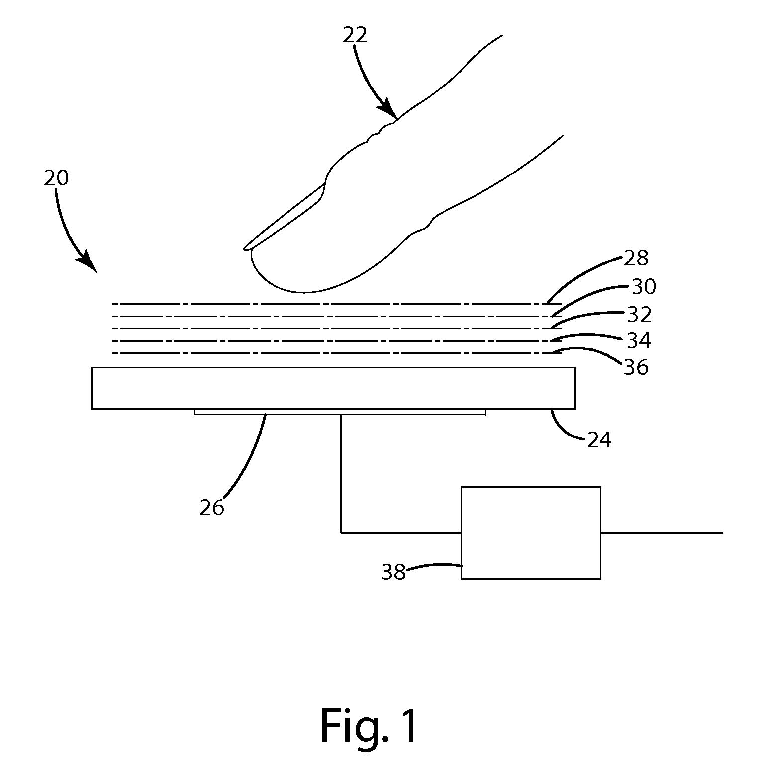
[0026]For example, consider again FIG. 1, which depicts a human finger 22 as moving toward a touch substrate 24, a capacitive sensor 26 and an associated measurement circuit 38. As the finger 22 is positioned at a first distance 28 relative to the substrate 24, the finger 22 is far enough from the capacitive sensor 26 that there is effectively no stimulus condition. If the finger 22 were moved closer at a second distance 30, there would be a slight amount of capacitive change at the capacitive sensor 26 and t...


PUM


Abstract

A capacitive sensor for detecting a stimulus. The capacitive sensor includes an electrode and a processing unit electrically coupled to the electrode and configured to determine the presence of a stimulus based on the rate of change of the electrode capacitance. A substrate is positioned adjacent the electrode, wherein the stimulus corresponds to the placement of an object against the substrate. The processing unit is operative to determine a time rate of change based on successive measurements of the electrode capacitance. In addition, the processing unit is operative to determine the presence of a stimulus in response to the time rate of change being less than a reference value.

Description

[0001]This application claims priority from provisional U.S. Application No. 61 / 163,237 filed Mar. 25, 2009, and entitled “Time Domain Differential Sensing.”FIELD OF THE INVENTION[0002]The present invention relates to an apparatus and method for sensing a touch input on a touch surface, and more particularly, to an electronic circuit and method for detecting a touch input.BACKGROUND OF THE INVENTION[0003]Touch inputs on a touch surface are widely used as an input methodology. Touch inputs may be best known in conjunction with appliance control panels, smart phones and other handheld devices. However, touch screens and touch inputs are gaining widespread acceptance as a user interface over a wide variety of applications. It is also important that a touch surface have an appropriate sensitivity to touch. If the surface is “too sensitive,” it may be susceptible to noise, or it may register false touches. If the surface is “too insensitive,” it may not accurately register desired touche...

Claims


Application Information

Patent Timeline
Patent Type & Authority Applications(United States)
IPC IPC(8): H03K17/96G01R27/26
CPCG06F3/0418G01R27/2605G06F3/041G06F3/044G06F3/0443
Inventor CALDWELL, DAVID W.SCHAEFER, WILLIAM D.
Owner ALSENTIS
Why Eureka
Try Eureka