Method for optically scanning and measuring a scene

a technology of optical scanning and scene, applied in the field of optical scanning and measuring a scene, can solve the problem that known methods cannot be used for fine registration, and achieve the effect of facilitating localization of targets, improving registration results, and reducing the number or required targets

Inactive Publication Date: 2012-03-22
FARO TECH INC
View PDF2 Cites 77 Cited by
  • Summary
  • Abstract
  • Description
  • Claims
  • Application Information

AI Technical Summary

Benefits of technology

[0007]In addition to the scans, it is also possible to use data from further measuring units, which are then linked with the scans. This may be an integrated measuring unit such as an inclination sensor or a compass, or an external measuring unit which, for example, carries out a conventional measurement. The registration results can thus be improved and / or the number or required targets can be reduced. It is, for example, also possible to determine the position of one or several targets by means of such measuring units. This facilitates localization of the targets in the scans or defines this localization.

Problems solved by technology

Those known methods can only be used for a fine registration (when no secondary minima exist).

Method used


Image

  • Method for optically scanning and measuring a scene
  • Method for optically scanning and measuring a scene
  • Method for optically scanning and measuring a scene

Examples


Embodiment Construction

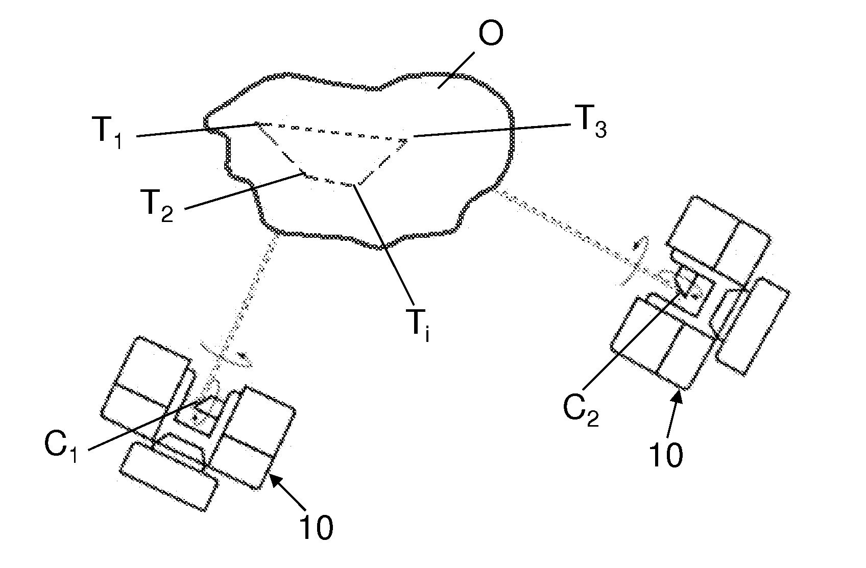
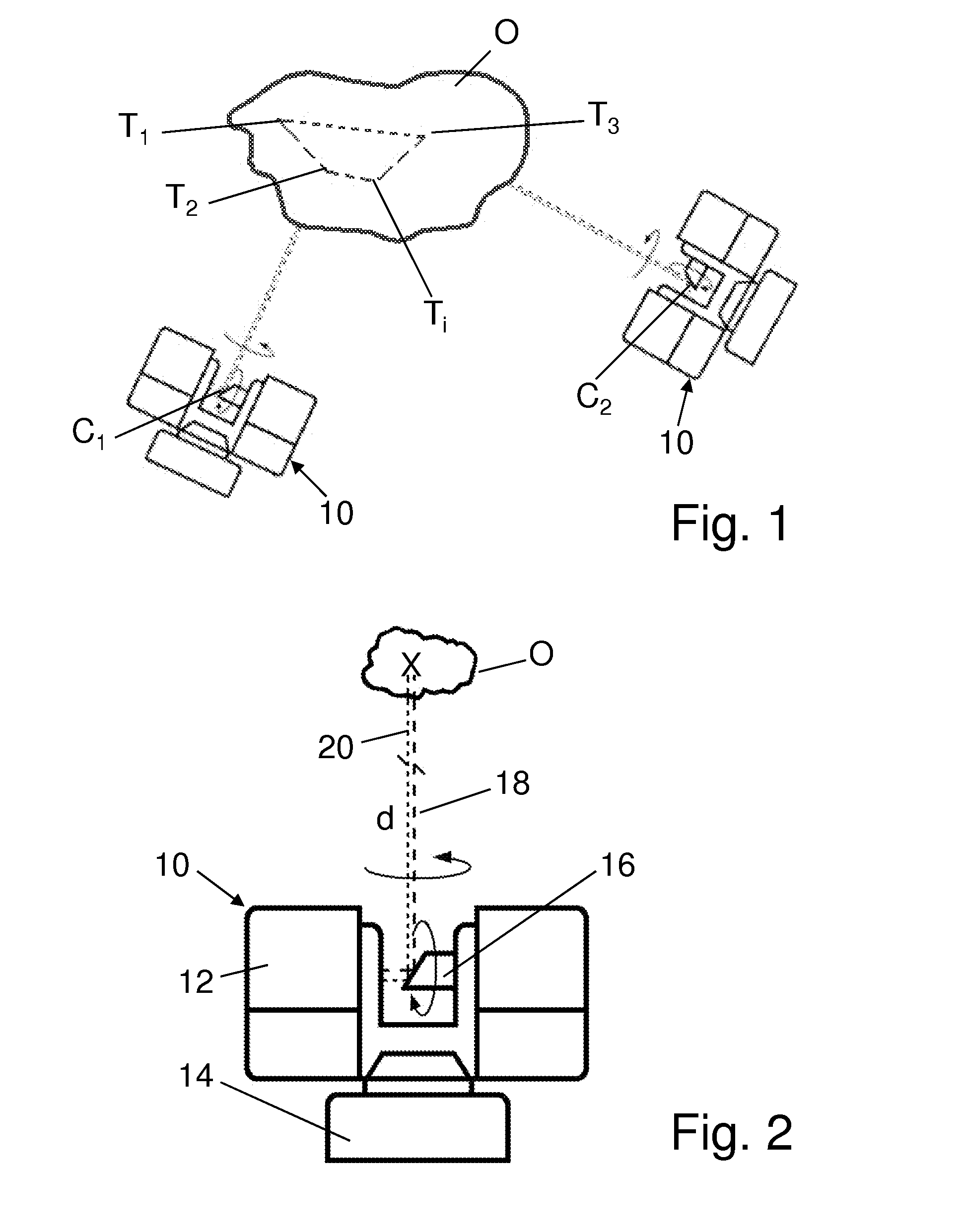
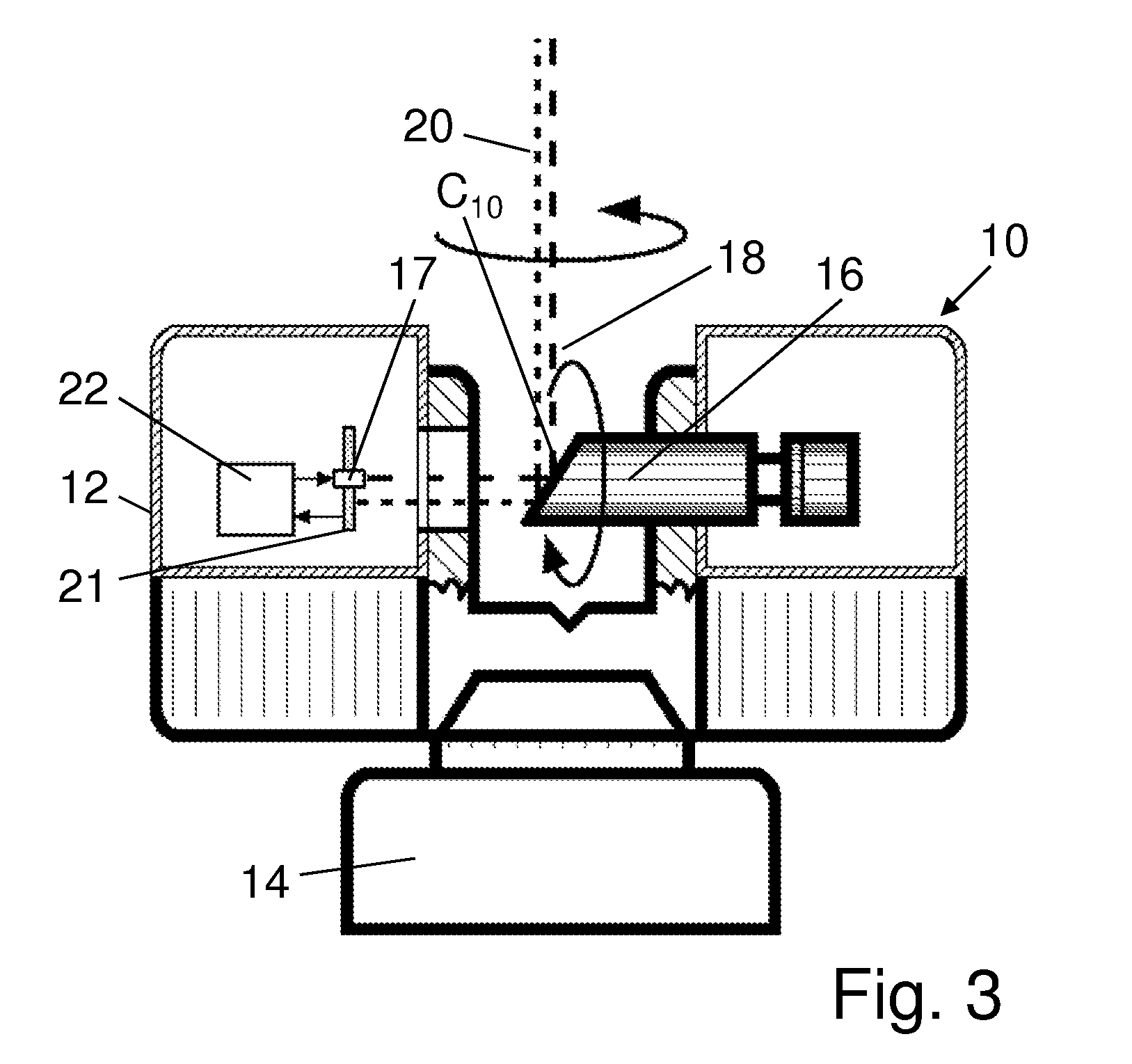
[0013]Referring to FIGS. 1-3, a laser scanner 10 is provided as a device for optically scanning and measuring the environment of the laser scanner 10. The laser scanner 10 has a measuring head 12 and a base 14. The measuring head 12 is mounted on the base 14 as a unit that can be rotated around a vertical axis. The measuring head 12 has a mirror 16, which can be rotated around a horizontal axis. The intersection of the two rotational axes is herein designated center Ci of the laser scanner 10.

[0014]The measuring head 12 is further provided with a light emitter 17 for emitting an emission light beam 18. The emission light beam 18 may be a laser beam in the visible range of approx. 300 to 1000 nm wavelength, such as 790 nm. Other electromagnetic waves having, for example, a greater wavelength can be used. The emission light beam 18 is amplitude-modulated, for example with a sinusoidal or with a rectangular-waveform modulation signal. The emission light beam 18 is emitted by the light ...


PUM


Abstract

A method for optically scanning and measuring a scene by means of a laser scanner which, for making a scan having a certain center, optically scans and measures its environment provided with targets, whereby two adjacent scans having different centers and scanning the same scene overlap within a range of measuring points so that some targets are scanned by any of the two scans, whereby, for registering the two adjacent scans, the targets are localized in the measuring points during a first step and, during a second step, candidates of correspondence among the localized targets of the two adjacent scans are looked for and, during a third step, a test registration of the two adjacent scans is made which, if there is a sufficient compliance of the measuring points within the overlapping range, is taken over for registration, thus identifying the targets.

Description

CROSS REFERENCE TO RELATED APPLICATIONS[0001]The present application is a National Stage Application of PCT Application No. PCT / EP2010 / 001781 filed on Mar. 22, 2010, which claims the benefit of U.S. Provisional Patent Application No. 61 / 299,103 filed on Jan. 28, 2010, and of pending German Patent Application No. DE 10 2009 015 922.3, filed on Mar. 25, 2009, and which are hereby incorporated by reference.BACKGROUND OF THE INVENTION[0002]The invention relates to a method for optically scanning and measuring a scene.[0003]By means of a laser scanner such as is known for example from U.S. Pat. No. 7,430,068, the surroundings of the laser scanner can be optically scanned and measured. To scan a larger scene, it may be necessary to make several scans from various positions, i.e. with different centers. Targets, which have been previously installed, and which are present in overlapping areas of two adjacent scans, are localized by a user and identified in the two adjacent scans.SUMMARY OF ...

Claims


Application Information

Patent Timeline
Patent Type & Authority Applications(United States)
IPC IPC(8): G01B11/24G01S17/89
CPCG01C3/06G01C15/002G06T2207/10028G01S17/89G06T7/0032G01S17/36G06T7/344
Inventor OSSIG, MARTINBECKER, REINHARDKRAMER, ALEXANDER
Owner FARO TECH INC
Why Eureka
Try Eureka