Sound direction estimation apparatus and sound direction estimation method

a technology of sound direction estimation and sound source, which is applied in direction finders, direction finders using ultrasonic/sonic/infrasonic waves, direction finders, etc., can solve the problem of not being able to estimate the direction of a specific class of sound sources, and achieve high precision

Active Publication Date: 2012-03-22
HONDA MOTOR CO LTD
View PDF3 Cites 16 Cited by
  • Summary
  • Abstract
  • Description
  • Claims
  • Application Information

AI Technical Summary

Benefits of technology

[0024]In the sound direction estimation apparatus according to the seventh aspect of the invention, it is possible to separate the sound signal by sound sources having different sound directions and to estimate the sound directions of the sound sources with high precision.

Problems solved by technology

However, the sound direction estimation apparatus described in JP-A-2010-281816 performs the processes regardless of sound classes and thus cannot estimate the direction of a sound source of a specific class.

Method used


Image

  • Sound direction estimation apparatus and sound direction estimation method
  • Sound direction estimation apparatus and sound direction estimation method
  • Sound direction estimation apparatus and sound direction estimation method

Examples


first embodiment

[0046]Hereinafter, a first embodiment of the invention will be described with reference to the accompanying drawings.

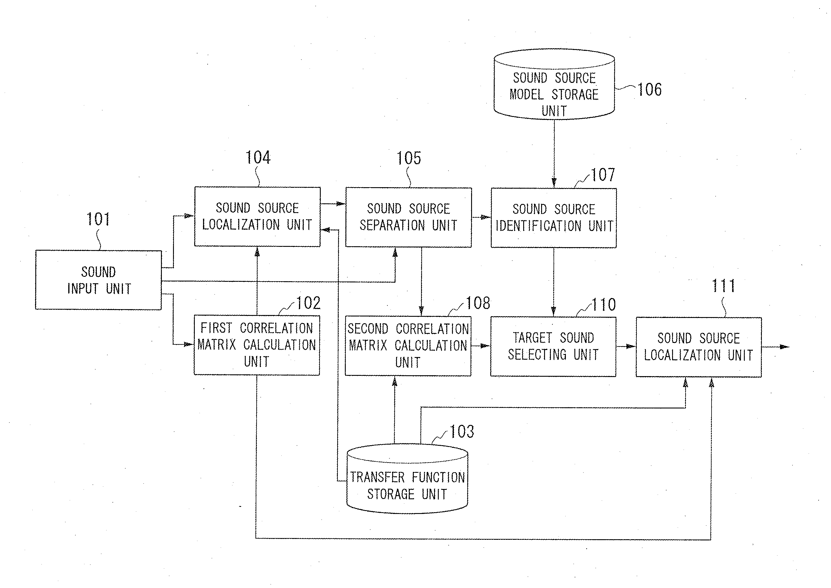
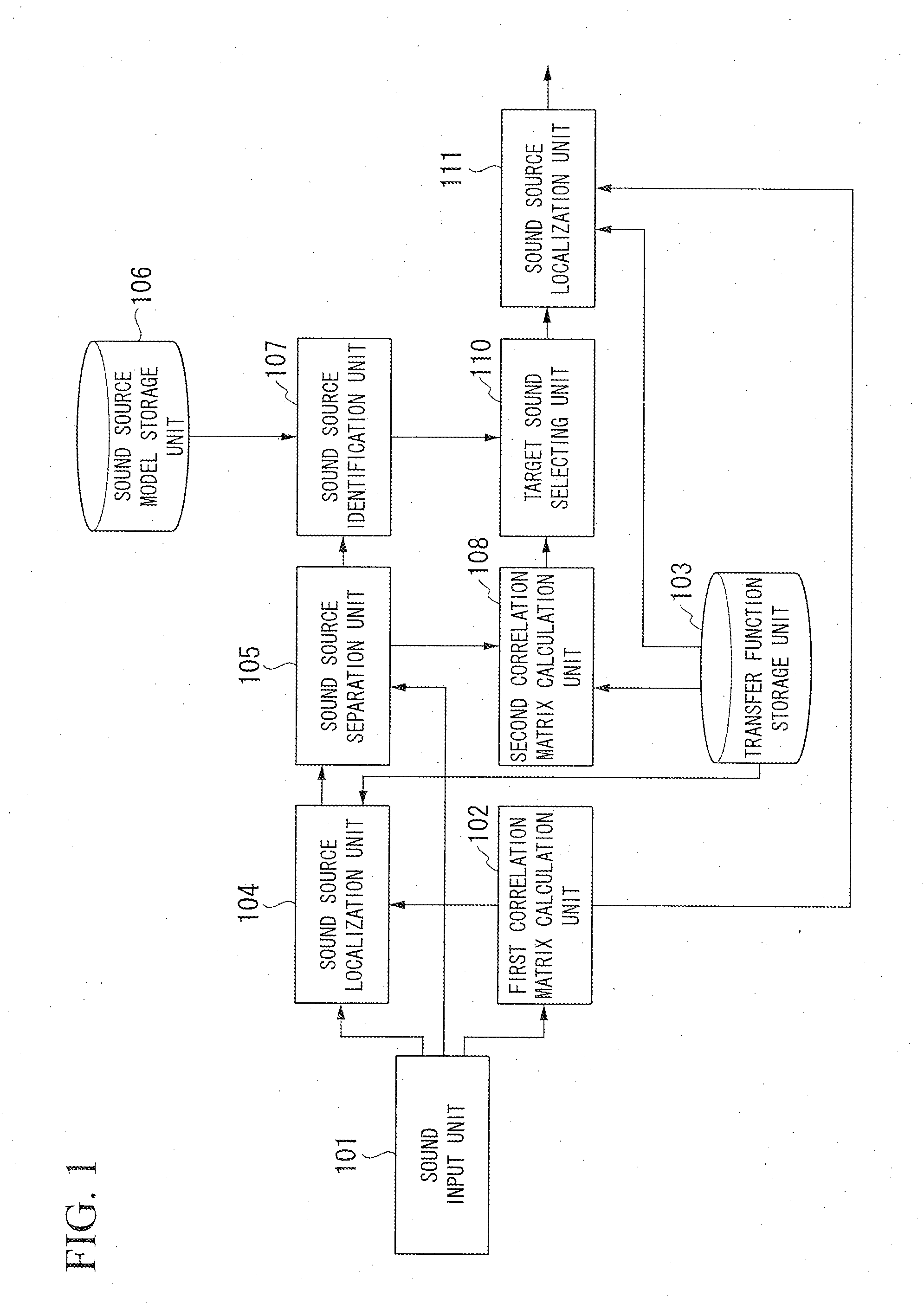
[0047]FIG. 1 is a diagram schematically illustrating the configuration of a sound direction estimation apparatus 1 according to the first embodiment of the invention. The sound direction estimation apparatus 1 includes a sound input unit 101, a first correlation matrix calculation unit 102, a transfer function storage unit 103, a sound source localization unit 104, a sound source separation unit 105, a sound source model storage unit 106, a sound source identification unit 107, a second correlation matrix calculation unit 108, a target sound selecting unit 110, and a sound source localization unit 111.

[0048]In this configuration, the sound source localization unit 104 estimates first sound direction information as primary candidates using a multiple signal classification (MUSIC) method. Note that a general MUSIC method may be referred to as a standard eigenvalue decom...

second embodiment

[0175]Hereinafter, a second embodiment of the invention will be described with reference to the accompanying drawings.

[0176]FIG. 8 is a diagram schematically illustrating the configuration of a sound direction estimation apparatus 2 according to the second embodiment of the invention.

[0177]The sound direction estimation apparatus 2 includes a sound input unit 101, a first correlation matrix calculation unit 102, a transfer function storage unit 103, a sound source localization unit 104, a sound source separation unit 105, a sound source model storage unit 106, a sound source identification unit 107, a second correlation matrix calculation unit 208, a correlation matrix information storage unit 209, a target sound selecting unit 110, a sound source localization unit 211, and a transfer function storage unit 212.

[0178]That is, the sound direction estimation apparatus 2 is different from the sound direction estimation apparatus 1 shown in FIG. 1, in that the second correlation matrix c...

third embodiment

[0228]Hereinafter, a third embodiment of the invention will be described with reference to the accompanying drawings.

[0229]FIG. 12 is a diagram schematically illustrating the configuration of a sound direction estimation apparatus 3 according to the third embodiment of the invention.

[0230]The sound direction estimation apparatus 3 includes a sound input unit 101, a first correlation matrix calculation unit 102, a transfer function storage unit 103, a sound source localization unit 104, a sound source separation unit 105, a sound source model storage unit 106, a sound source identification unit 107, a second correlation matrix calculation unit 308, a correlation matrix information storage unit 209, a target sound selecting unit 310, a sound source localization unit 211, and a transfer function storage unit 212.

[0231]That is, the sound direction estimation apparatus 3 is different from the sound direction estimation apparatus 1 shown in FIG. 1, in that the second correlation matrix ca...


PUM


Abstract

A sound direction estimation apparatus includes a sound source model storage unit that stores likelihood of a sound source class in correspondence with a sound feature quantity, a sound signal input unit that receives a sound signal, a sound source identification unit that identifies a sound source class of the sound signal input from the sound signal input unit with reference to the sound source model storage unit based on the sound feature quantity of the sound signal, and a first sound source localization unit that estimates a sound direction of the sound signal of the sound source class identified by the sound source identification unit.

Description

CROSS REFERENCE TO RELATED APPLICATIONS[0001]This application claims benefit from U.S. Provisional application Ser. No. 61 / 374,376, filed Aug. 17, 2010, and U.S. Provisional application Ser. No. 61 / 374,380, filed Aug. 17, 2010, the contents of which are incorporated herein by reference.BACKGROUND OF THE INVENTION[0002]1. Field of the Invention[0003]The present invention relates to a sound direction estimation apparatus and a sound direction estimation method.[0004]2. Description of Related Art[0005]With the advancement in robotics technology, robots having artificial intelligence have been developed. These robots are expected to have faculty in recognizing a command given by a person or faculty in understanding surrounding circumstances. An example of surrounding circumstances is the direction of a sound source. Regarding a sound direction estimation technique employed by a humanoid robot, a sound direction estimation apparatus described in JP-A-2010-281816 is known.[0006]The sound ...

Claims


Application Information

Patent Timeline
Patent Type & Authority Applications(United States)
IPC IPC(8): G01S3/80
CPCG01S3/8006
Inventor NAKADAI, KAZUHIRONAKAMURA, KEISUKE
Owner HONDA MOTOR CO LTD
Why Eureka
Try Eureka