Transmitter device, receiver device, and wireless communication system

a technology of transmitter device and receiver device, applied in the direction of transmission monitoring, receiving device monitoring, line-transmission details, etc., can solve the problem of increasing transmission power, and achieve the effect of preventing an increase in control information

Inactive Publication Date: 2012-03-22
SHARP KK
View PDF7 Cites 8 Cited by
  • Summary
  • Abstract
  • Description
  • Claims
  • Application Information

AI Technical Summary

Benefits of technology

[0032]With the present invention, with respect to a wireless communication system employing ILP, by mapping coefficient α, which is used in common at a transmitter device and a receiver device, to the MCS that is to be applied to data communications from the transmitter device to the receiver device, it becomes unnecessary to add control information for notifying coefficient α, and it is thus possible to prevent an increase in control information.

Problems solved by technology

However, there was a problem with thus subtracting the interference signal component from the transmission signal in that the transmission power would increase with the interference signal power.

Method used


Image

  • Transmitter device, receiver device, and wireless communication system
  • Transmitter device, receiver device, and wireless communication system
  • Transmitter device, receiver device, and wireless communication system

Examples


first embodiment

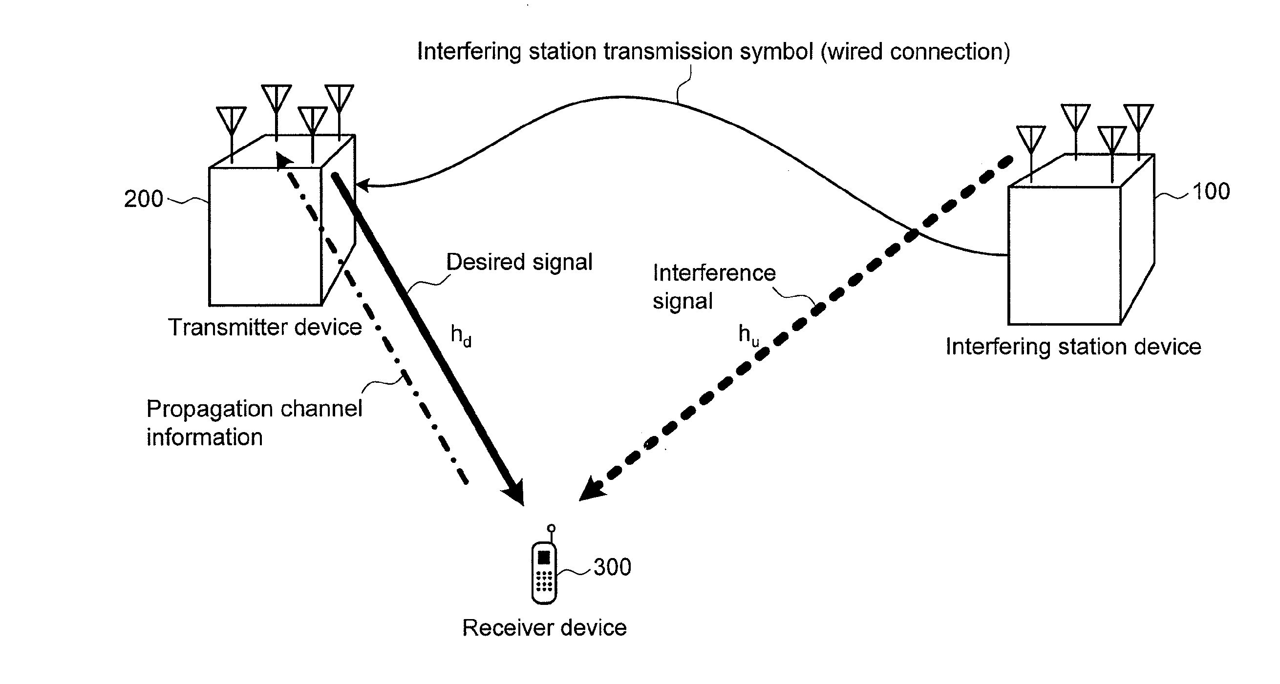
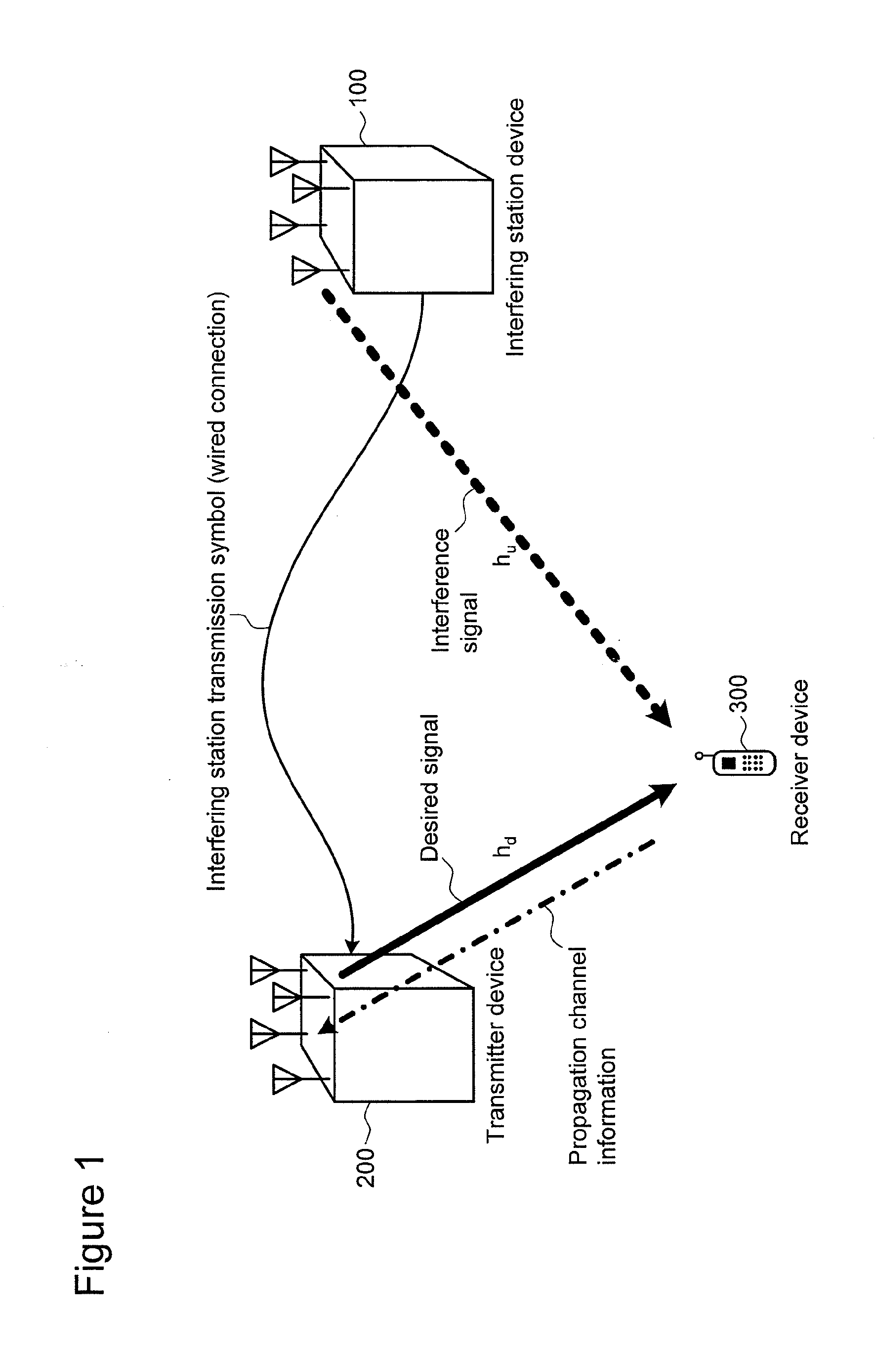
[0051]FIG. 1 is a figure showing a schematic configuration example of a wireless communication system with respect to the first embodiment of the present invention.

[0052]As shown in FIG. 1, for a wireless communication system with respect to the present embodiment, there is assumed a wireless communication in which, with respect to a desired signal with which a transmitter device 200 transmits data to a receiver device 300, a signal transmitted by an interfering station device 100 is received by the receiver device 300 as an interference signal. A specific example might include a case where, with respect to two base station devices (or relay station devices, etc.) that constitute different cells or sectors in a cellular system, there exists a terminal device that communicates with one of those base station devices, and a signal that the other base station device transmits to another terminal device is received by the terminal device.

[0053]The transmitter device 200 is, in advance an...

second embodiment

[0096]FIG. 8 is a functional block diagram showing a configuration example of a transmitter device 200a with respect to the second embodiment of the present invention. A description will be provided here only with respect to parts that differ from the transmitter device 200 in FIG. 2, while omitting descriptions for like parts.

[0097]A coefficient table information acquisition part 35 detects coefficient table information notified by a receiver device 300a, which is included in the signal received by the wireless receiver part 3 via the antenna part 1. If coefficient table information is detected, the detected coefficient table information is outputted to a coefficient table part 21a.

[0098]Once coefficient table information is inputted, the coefficient table part 21a replaces the coefficient table it holds with the inputted coefficient table information.

[0099]FIG. 9 is a functional block diagram showing a configuration example of the receiver device 300a with respect to the second e...

third embodiment

[0117]FIG. 12 is a functional block diagram showing a configuration example of a transmitter device 200b with respect to the third embodiment of the present invention. A description will be provided here only with respect to parts that differ from the transmitter device 200a in FIG. 8, while omitting descriptions for like parts.

[0118]A response acquisition part 37 detects a positive response indicating the fact that reception has been carried out successfully (ACK: Acknowledgment) or a negative response indicating the fact that reception has not been carried out successfully (NACK: Negative Acknowledgment), which is notified from a receiver device 300b and contained in a signal received by the wireless receiver part 3 via the antenna part 1.

[0119]If the error rate of the reception data measured at the response acquisition part 37 is higher than the requisite error rate (many errors), or if it falls far below the requisite error rate (few errors), a table update request generator par...


PUM


Abstract

With respect to a wireless communication system comprising a transmitter device 200, which is equipped with a function for performing inflated lattice precoding (ILP) on transmission data, and a receiver device 300, which receives a signal transmitted from the transmitter device and restores data, there is adopted a feature wherein “coefficient α” which is required when the transmitter device 200 performs the above-mentioned ILP, and which is also required when the receiver device performs data restoration, is uniquely derived using information relating to an MCS (modulation parameter) that is applied with respect to the wireless communication system (more specifically, a feature wherein a “coefficient table part,” which uniquely maps MCS information to coefficient α, is provided at both the transmitter device and the receiver device, and wherein coefficient α required at both the transmitter device and the receiver device is derived using this “coefficient table part”), thereby evading having to exchange information relating to “coefficient α” between the transmitter device and the receiver device.

Description

TECHNICAL FIELD[0001]The present invention relates to a transmitter device, receiver device and wireless communication system which perform wireless communication with interference suppressed.BACKGROUND ART[0002]With respect to communication systems, if a transmitter device is able to know in advance the interference signal component contained in the reception signal of a receiver device, it is possible to have the receiver device be substantially unaffected by interference, by subtracting (cancelling) the interference signal component from the transmission signal at the transmitter device in advance.[0003]However, there was a problem with thus subtracting the interference signal component from the transmission signal in that the transmission power would increase with the interference signal power. In order to solve this problem, there has been proposed a method referred to as Tomlinson-Harashima Precoding (THP) which is capable of suppressing the increase in transmission power by p...

Claims


Application Information

Patent Timeline
Patent Type & Authority Applications(United States)
IPC IPC(8): H04B15/00H04B1/10H04B1/04H04B1/3822H04B1/40H04B3/04H04B7/005H04B17/24H04B17/309H04J99/00H04L27/00H04W24/04H04W28/18
CPCH04L1/0034H04L27/34H04L1/0035
Inventor ONODERA, TAKASHINAKANO, HIROSHIHIRATA, KOZUEKUBOTA, MINORU
Owner SHARP KK
Why Eureka
Try Eureka