Syringe drive device and medication dispensing device

a drive device and drive technology, applied in the direction of pharmaceutical containers, packaging foodstuffs, packaged goods, etc., can solve the problems of increasing the operation time, demanding the task of dispensing operations, and high labor intensity, and achieves remarkable operability, reduce or increase the internal pressure, and easy aspiration

Inactive Publication Date: 2012-03-22
PANASONIC CORP
View PDF1 Cites 72 Cited by
  • Summary
  • Abstract
  • Description
  • Claims
  • Application Information

AI Technical Summary

Benefits of technology

[0012]An operator who uses the syringe drive device according to the present invention holds a grip portion with one hand to hold the syringe drive device mounted with the syringe. Then, the operator is able to move the syringe piston in the direction where the piston is pushed in or pulled out by inputting an instruction to an instruction input section while holding the syringe drive device. Simply by inputting an instruction whatever necessary to the instruction input section while holding the syringe drive device mounted with the syringe with one hand, the operator can easily aspirate the medicinal solution or air from the medicinal solution container into the syringe or inject the medicinal solution or air from the syringe into the medicinal solution container. This technical advantage of the syringe drive device according to the present invention exerts a remarkable operability in a medication dispensing operation such as mixing medication ingredients. Further, the internal pressure of the medicinal solution container measured by an internal pressure gauge is displayed on the display section. The operator who dispenses the medication can input an instruction to the instruction input section to move the piston in the direction where the piston is pushed in or pulled out while checking the internal pressure displayed on the display section. This technical advantage enables the operator to aspirate or inject the medicinal solution reliably and readily between the medicinal solution container and the syringe without overly decreasing or increasing the internal pressure of the medicinal solution container. The syringe drive device according to the present invention can effectively support the operator who dispenses the medication such as mixing medication ingredients.

Problems solved by technology

It is difficult and time-consuming to extract the medicinal solution alone from the medicinal solution containing the air bubbles, significantly increasing an operation time and thereby making the operation very inefficient.
However, it is a very demanding task to perform the dispensing operation, which requires a high level of concentration, over long hours.
In view of at least these technical disadvantages, the device disclosed in the Patent Document 1 fails to teach any distinctive means effective for supporting the dispensing operation using the syringe.

Method used


Image

  • Syringe drive device and medication dispensing device
  • Syringe drive device and medication dispensing device
  • Syringe drive device and medication dispensing device

Examples


embodiment 1

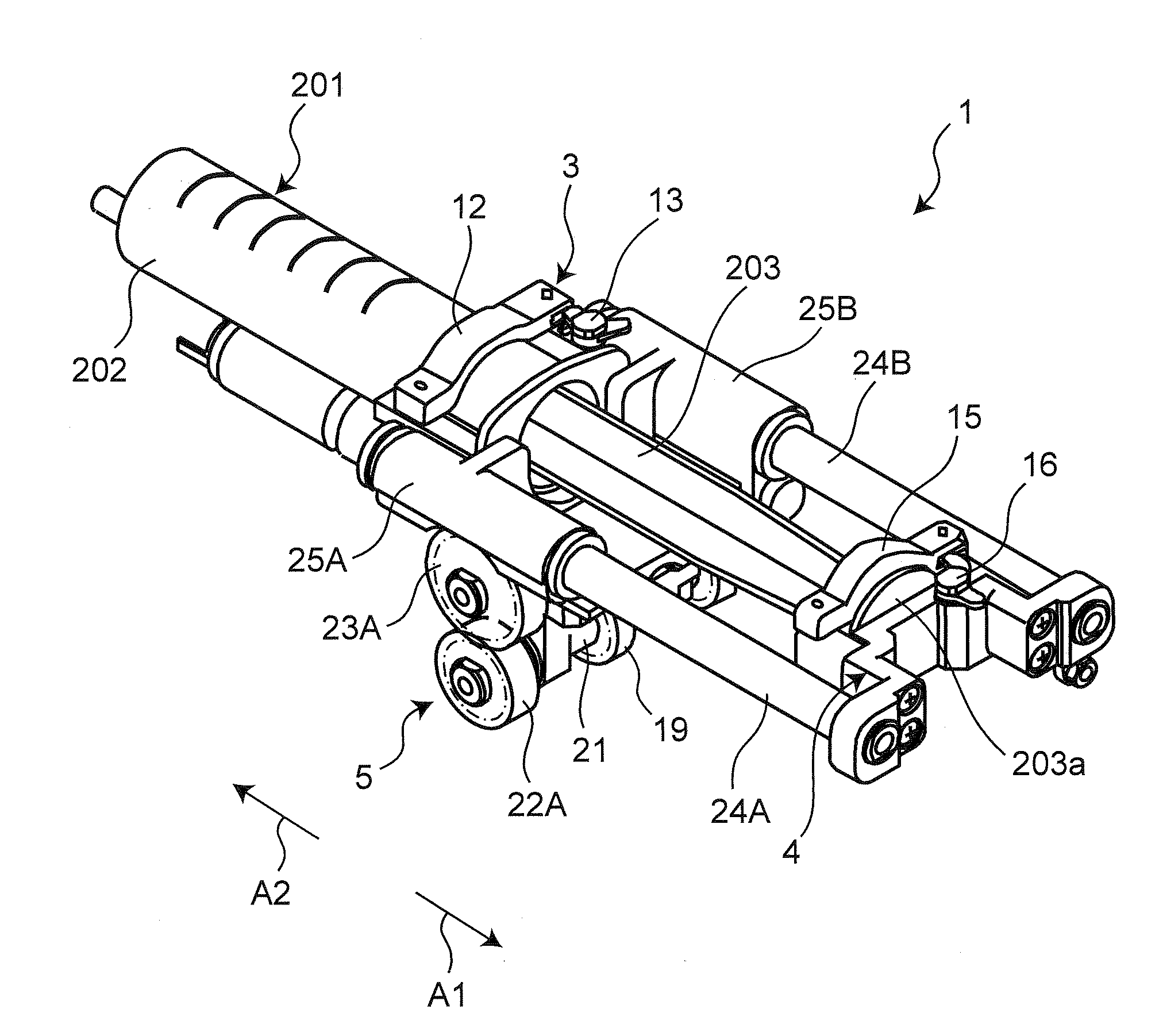
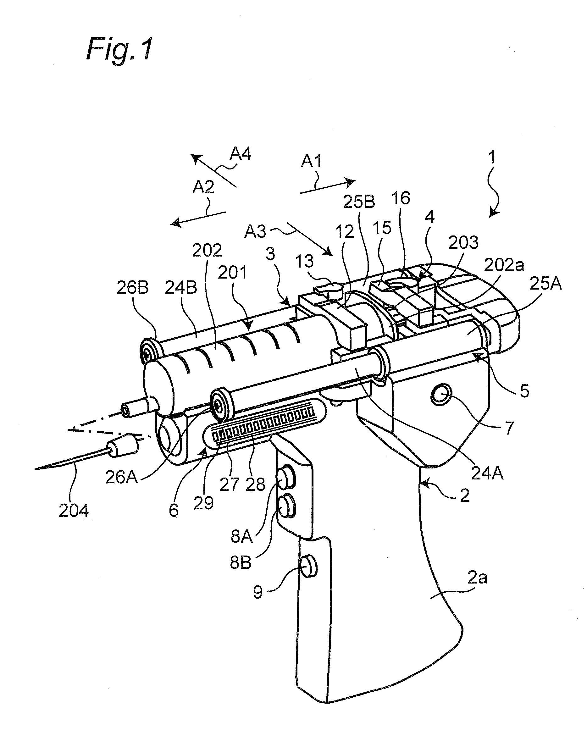
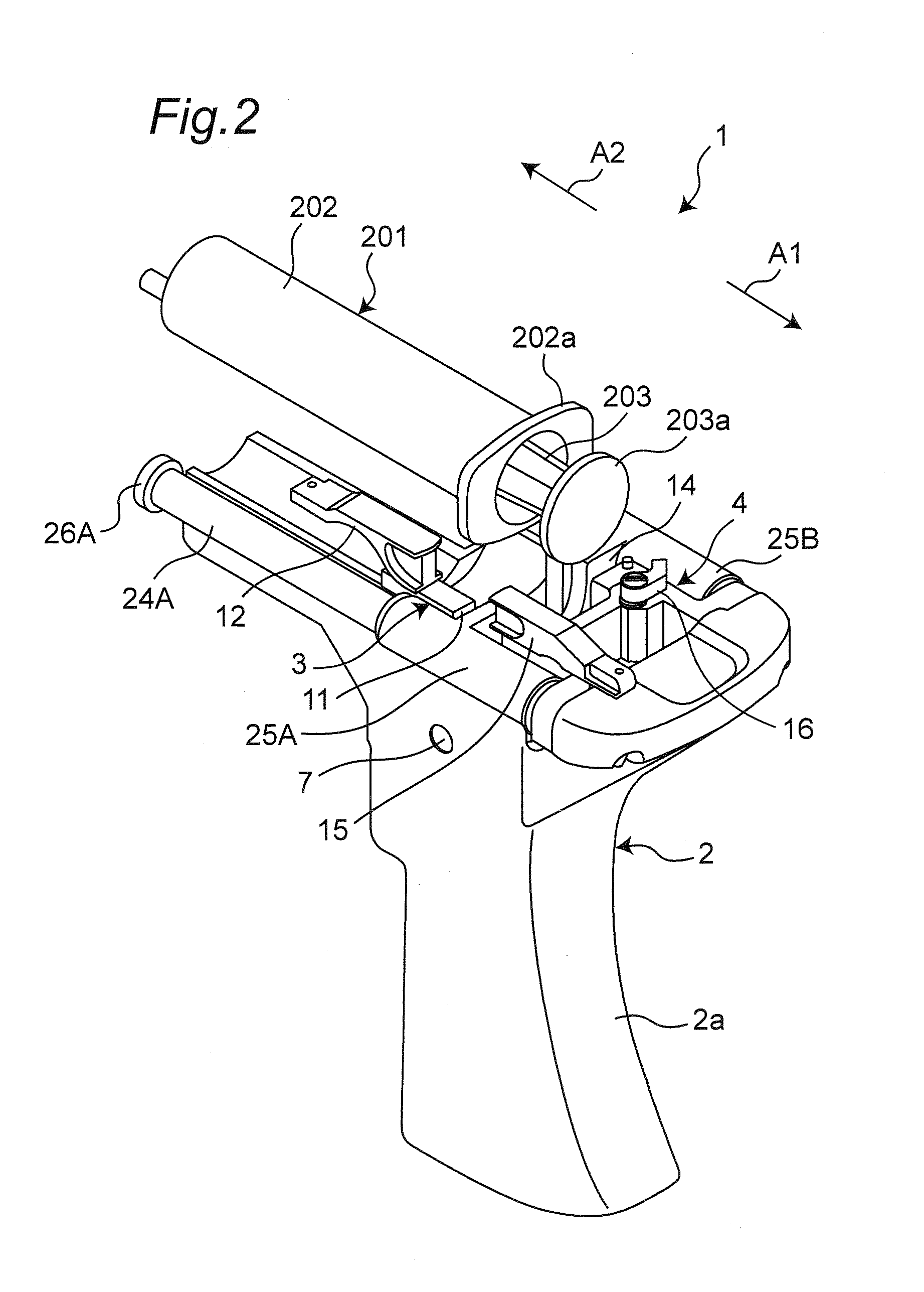
[0031]FIGS. 1 and 2 are perspective views of a syringe drive device 1 according to an embodiment 1 of the present invention. The syringe drive device 1 is designed to support an operator who dispenses a medication using a syringe 201. An example of the medication dispensing operation is a mixing operation to prepare, for example, an injection solution or an intravenous solution. Examples of the medication dispensing operation according to the present embodiment are; aspirating a medicinal solution from a vial 301 (see FIGS. 8A and 8B) which is a medicinal solution container into a syringe 201, and injecting a medicinal solution from the syringe 201 into the vial 301. The syringe 201 is provided with an outer tube 202 mounted with an injection needle 204 on an edge thereof, and a piston 203, an edge of which provided with a gasket (not illustrated in the drawing) is inserted in the outer tube 202 through an opening on the opposite side of the injection needle 204. A flange portion 20...

embodiment 2

[0087]In the embodiment 1, the internal pressure of the vial 301 is calculated from the drive current of the motor 17. An embodiment 2 of the present invention illustrated in FIGS. 9 and 10 is different from the embodiment 1 in that the piston manipulating section 4 detects a stress received from the piston 203 and calculates the internal pressure of the vial 301 based on the detected stress. More specifically, a body 402 of a syringe drive device 401 according to the present embodiment is provided with a stress detecting section 52. The stress detecting section 52 has stress sensors 51A and 51B attached to a groove wall of the groove 14 of the piston manipulating section 4. As described earlier, the jaw portion 203a of the piston 203 is fitted in the groove 14 of the piston manipulating section 4, and the coupling piece 15 at the closing position is engaged with the locking claw 16 so that the piston is coupled with the piston manipulating section 4. Then, when a load in the pull-o...

embodiment 3

[0090]FIG. 12 illustrates a medication dispensing apparatus 61 to which the syringe drive device according to the present invention is applied. The medication dispensing apparatus 61 is configured to aspirate and inject the medicinal solution to and from the syringe 201 and the vial 301. The operator can perform the aspirating and injection by simply manipulating the medication dispensing apparatus 61 without holding the syringe 201 or the vial 301 with hand.

[0091]A movable section 62 of the medication dispensing apparatus 61 has a syringe drive device holding section 67 configured to hold a syringe drive device 1 similar to that of the embodiment 1 on one end thereof, and a container holding section 63 on the other end thereof. The container holding section 63 has openable and closable clamps 64A and 64B configured to detachably hold the medicinal solution container (vial 301 in the given example). The container holding section 63 linearly reciprocates to and from the movable secti...


PUM


Abstract

A syringe drive device 1 includes: a syringe holding section 3; a piston manipulating section 4; and a display section 6. An outer tube 202 of a syringe 201 is detachably held by the syringe holding section 3. A piston 203 of the syringe 201 is detachably engaged with the piston manipulating section 4. The piston manipulating section 4 moves in a direction in response to an operation of operation buttons 8A and 8B, and the piston 203 is thereby moved in a direction where the piston is pushed into or pulled out from the outer tube 202. An internal pressure of a medicinal solution container punctured with an injection needle 204 attached to the outer tube 202 of the syringe 201 is measured and displayed on the display section 6.

Description

TECHNICAL FIELD[0001]The present invention relates to a syringe drive device configured to move a piston (plunger) of a syringe, which is used in a medication dispensing operation, such as a mixing operation to prepare an injection solution or an intravenous solution, relative to an outer tube (barrel). The present invention further relates to a medication dispensing apparatus to which such a syringe drive apparatus is applied.BACKGROUND ART[0002]In a conventional mixing operation to prepare an injection solution or an intravenous solution, aspirating a medicinal solution in a vial (medicinal solution container) into a syringe or injecting a medicinal solution in a syringe into a vial is manually carried out by an operator. In these processes, an injection needle attached to an edge of the syringe is punctured into a rubber cap of the vial so that the inside of the syringe and the vial form an enclosed space.[0003]When the medicinal solution contained in the vial is aspirated into t...

Claims


Application Information

Patent Timeline
Patent Type & Authority Applications(United States)
IPC IPC(8): A61M5/20
CPCA61J1/20A61J1/2096A61J2001/201A61M2005/3125A61M5/3148A61M5/486A61M5/20A61J1/201
Inventor TOJO, TSUYOSHIFUJIOKA, SOICHIRONAKAMURA, TOHRU
Owner PANASONIC CORP
Why Eureka
Try Eureka