Flowable hydrogels for control of cell in-migration

a technology of hydrogels and cell in-migration, which is applied in the field of hydrogel formation, can solve the problems of inability to routinely use pain in the eye caused by trauma or surgery, and the general progress of bandages between the eye and the eyelid, so as to achieve continuous coverage of the wound, the effect of reducing discomfort and complications

Active Publication Date: 2012-03-22
INCEPT LLC
View PDF3 Cites 43 Cited by
  • Summary
  • Abstract
  • Description
  • Claims
  • Application Information

AI Technical Summary

Benefits of technology

[0003]Disclosed herein are hydrogel bandages for placement on an eye. The hydrogels may be formed directly on the eye from precursor materials that react with each other to form the hydrogel on the eye. The bandage adheres directly to the eye to minimize discomfort and complications that could result from movement of the bandage around the eye. The hydrogel can be made with an unexpected property: displacement from the eye by cell in-migration. The cells are unable to grow over or under the hydrogel. The hydrogel degrades and is displaced from its outside edges inwardly by epithelial cells. The interplay between the changing mechanical strength of the hydrogel and the activity of the epithelial cells are approximately matched. As a result, the wound edges are healed as the hydrogel withdraws from the wound, to thereby provide continuous coverage of the wound. These and other embodiments are set forth herein.

Problems solved by technology

A wound on the surface of the eye caused by trauma or surgery can often be painful.
The arts of applying a bandage between the eye and the eyelid, however, have generally not advanced to the point where such bandages can be routinely used.

Method used


Image

  • Flowable hydrogels for control of cell in-migration
  • Flowable hydrogels for control of cell in-migration
  • Flowable hydrogels for control of cell in-migration

Examples


example 1

Test Conditions, Hydrogel Swelling (Shrinkage) and Degradation for Hydrogels

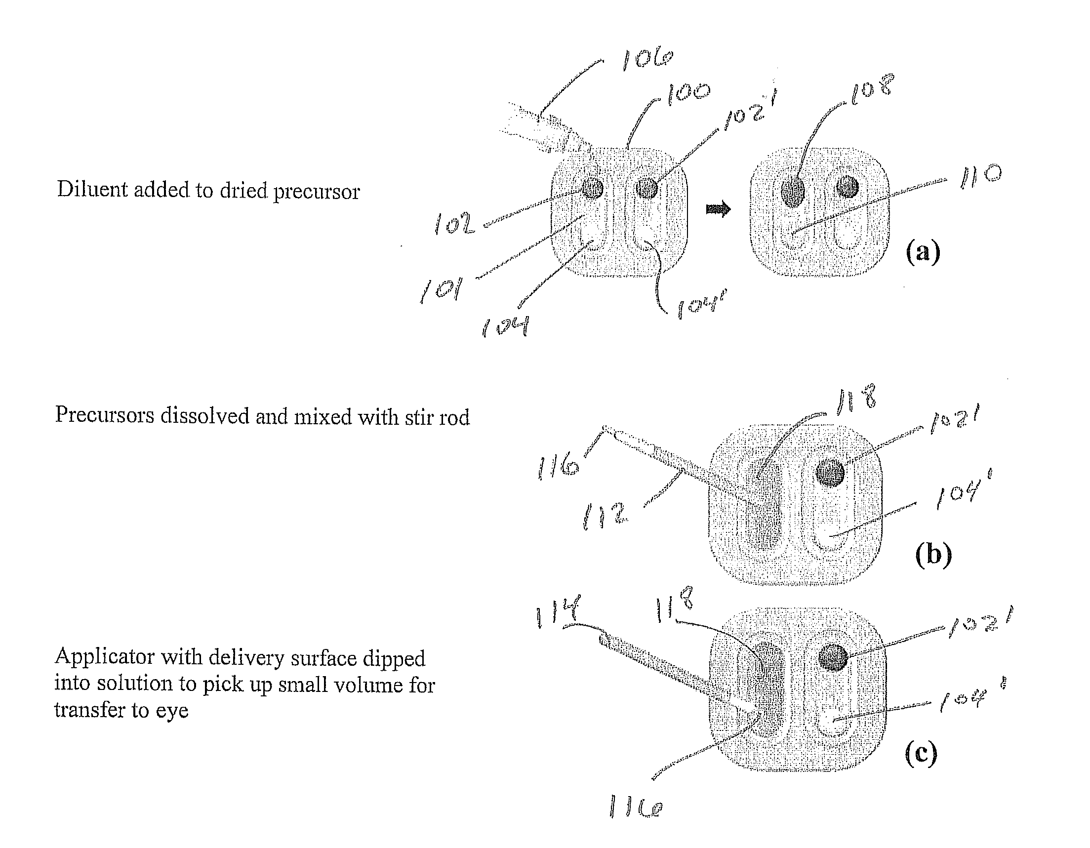
[0121]One deposit consisted of 8 arm 15K SG PEG (8.7 mg), sodium phosphate monobasic buffer, and FD&C Blue #1 (0.01 mg). The other deposit consisted of trilysine acetate (0.52 mg), sodium phosphate dibasic and sodium tetraborate decahydrate. Water volumes were varied with WFI from 40 μl to 280 μl in 40 μl increments to provide a range of gels with varied solids content. The succinimidyl glutarate:amine ratio was 1:1. Degradation In Vitro Phosphate Buffered Saline (PBS) was added to vials containing the gels. The vials were then transferred to a 37° C. water bath for degradation. The degradation process as tracked by daily visual inspection until complete disappearance of the sample was observed.

[0122]Gel time testing Gel time was tested using a polycarbonate rod (2 inch long and one-eighth inch diameter) to stir the two solutions within the tray well and then lifting the rod 3 inches every second. Gel time (...

example 2

Hydrogel Swelling (Shrinkage) and Degradation for Alternative Hydrogels

[0126]The materials and methods of Example 1 were used except that a buffered diluent was used instead of WFI to make the solution in order to minimize the effect of diluent on the gel time of the composition. For that reason, both sodium phosphate dibasic and sodium tetraborate decahydrate salts were changed from being dried deposits in Example 1 to being dissolved in solution with water for injection to make the diluent in Example 2. Gels were prepared by adding diluent to each deposit, then mixing the two together. Diluent volumes were varied from 160 μl to 320 μl in 40 μl increments to provide a range of gels with varied solids content. The results are shown in Table 2.

[0127]This formulation was diluted with a diluent rather than water as in the Series 1 formulation. Since the diluent contained sodium phosphate dibasic and sodium tetraborate decahydrate, it was basic in pH additional diluent resulted in less ...

example 3

Hydrogel Swelling (Shrinkage) and Degradation for Alternative Hydrogels

[0128]Another alternative hydrogel formulation, series 3, was tested as in Example 2. The formulation used in series 3 was essentially identical to that used in Example 2, with the exception of the polyethylene glycol (PEG) macromer. In series 3, the macromer end groups were changed from glutarate (SG) to succinate (SS). The base polymer was an 8 arm 15K PEG SS molecule. The results of this testing are shown in Table 3.

[0129]As in Example 2, the effect of dilution is smaller than in Example 1. In fact, Example 3 showed no effect of dilution over the range studied. It should be noted that a Example 2 formulation at a dilution of 80 μl, typically gels in 25 seconds. The Example 2 material in Table 3 shows that at 160 μl dilution the gel time is still about 25 seconds, which agrees with the results for Example 3 in Table 3.

TABLE 3The effect of dilution on gel time and degradation for Series 3Diluent Solids Gel Time ...


PUM

PropertyMeasurementUnit
depthaaaaaaaaaa
heightaaaaaaaaaa
volumeaaaaaaaaaa

Abstract

Materials and methods of treating an eye with a hydrogel formed on the eye. Embodiments are provided that include post-keratectomy bandages.

Description

TECHNICAL FIELD[0001]The technical field relates to formation of hydrogels on an ocular surface for treatment of an eye, and includes particular methods of applying the hydrogels as well as particular compositions of the same.BACKGROUND[0002]A wound on the surface of the eye caused by trauma or surgery can often be painful. Brushing of the eyelid against the eye can aggravate pain caused by the damage. The arts of applying a bandage between the eye and the eyelid, however, have generally not advanced to the point where such bandages can be routinely used.SUMMARY OF THE INVENTION[0003]Disclosed herein are hydrogel bandages for placement on an eye. The hydrogels may be formed directly on the eye from precursor materials that react with each other to form the hydrogel on the eye. The bandage adheres directly to the eye to minimize discomfort and complications that could result from movement of the bandage around the eye. The hydrogel can be made with an unexpected property: displacemen...

Claims


Application Information

Patent Timeline
Patent Type & Authority Applications(United States)
IPC IPC(8): A61B18/20A61P27/02A61P29/00A61K9/00
CPCA61K9/0048A61K47/34A61K9/06A61P27/02A61P29/00
Inventor JARRETT, PETERHAYEK, RAMI ELBASSETT, MICHAELBIGGINS, JAMES
Owner INCEPT LLC
Why Eureka
Try Eureka