Method of manufacturing thermal head

Inactive Publication Date: 2012-03-29
SEIKO INSTR INC
View PDF2 Cites 2 Cited by
  • Summary
  • Abstract
  • Description
  • Claims
  • Application Information

AI Technical Summary

Benefits of technology

[0007]The present invention has been made in view of the above-mentioned circumstances, and it is an object thereof to provide a method capable of manufacturing a thermal head having high heating efficiency and stable quality.

Problems solved by technology

Further, the concave portion and the upper substrate are disposed under the heating resistors, the electrodes, the protective film, and the like, and hence the dimensions cannot be measured or corrected at a final stage after the thermal head is assembled.
Therefore, the conventional manufacturing method has a problem that fluctuations in heating efficiency cannot be suppressed and it is difficult to manufacture a thermal head having stable quality.

Method used


Image

  • Method of manufacturing thermal head
  • Method of manufacturing thermal head
  • Method of manufacturing thermal head

Examples


Embodiment Construction

[0031]Now, a method of manufacturing a thermal head according to an embodiment of the present invention is described below with reference to the accompanying drawings.

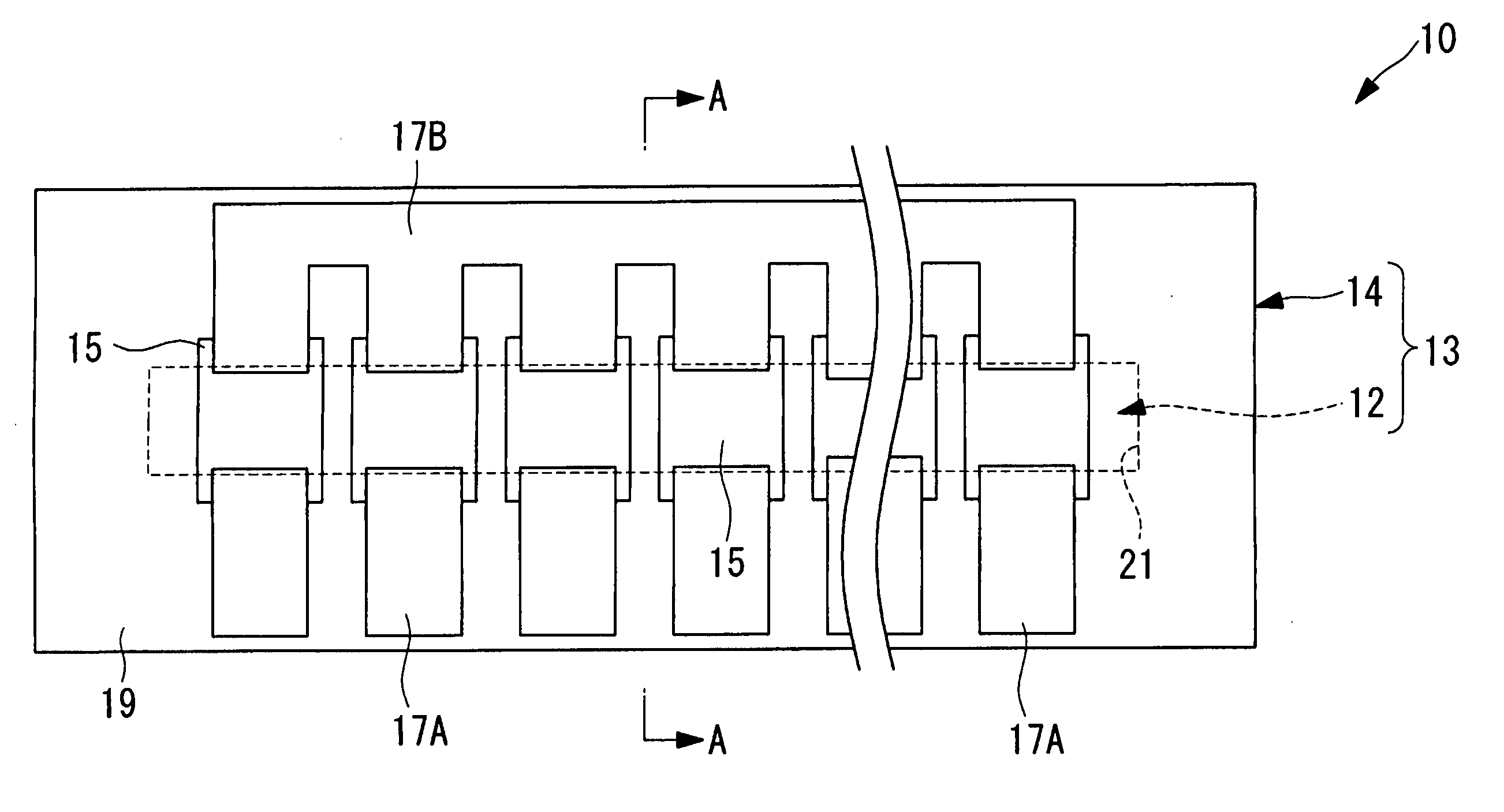
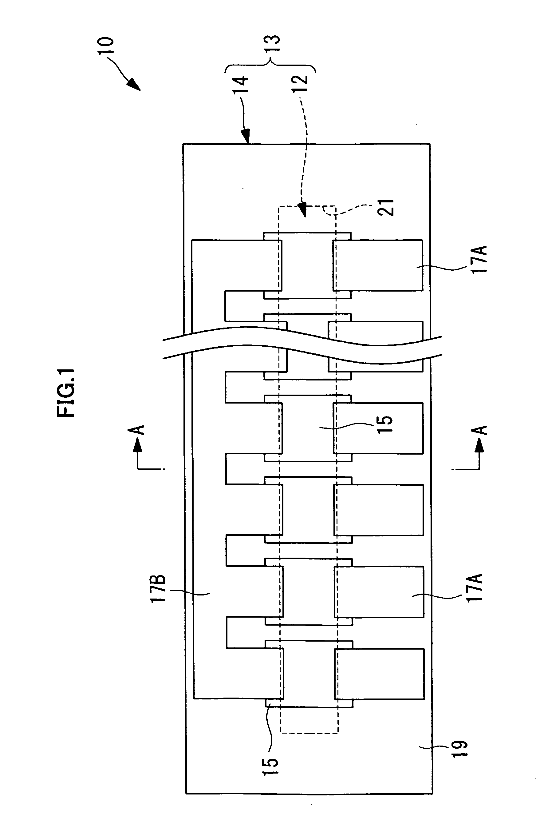
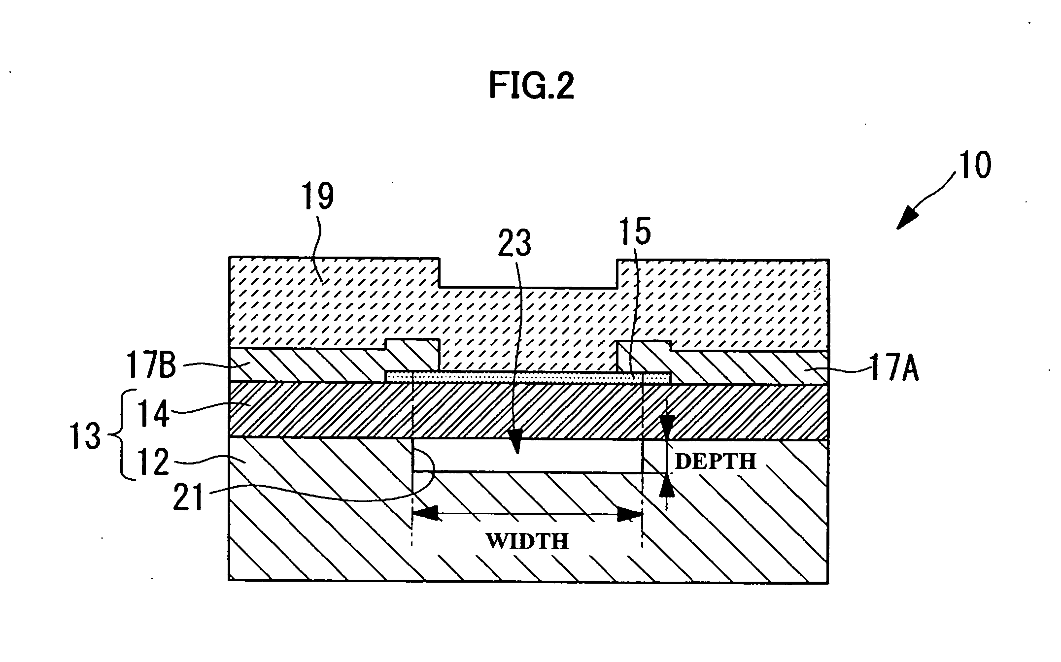
[0032]The method of manufacturing a thermal head according to this embodiment is for manufacturing, for example, as illustrated in FIGS. 1 and 2, a thermal head 10 for use in a thermal printer (not shown). In this embodiment, description is given of a method of manufacturing a plurality of thermal heads 10 from a large-size support substrate (first substrate) 12 and a large-size upper substrate (second substrate) 14 as illustrated in FIGS. 3A and 3B.

[0033]The manufacturing method of this embodiment includes, as illustrated in a flowchart of FIG. 4, a concave portion forming step (groove portion forming step) SA1 of forming a plurality of concave portions (groove portions) 21 each opened in one surface of the plate-shaped support substrate 12, a concave portion measuring step (groove measuring step) SA2 of measuring a w...


PUM

PropertyMeasurementUnit
Thicknessaaaaaaaaaa

Abstract

A method of manufacturing a thermal head, comprising: forming a concave portion opened in one surface of at least one of a support substrate and an upper substrate to be disposed on the support substrate in a stacked state, the support substrate and the upper substrate each being of a plate shape; measuring a width dimension of the concave portion; bonding the support substrate and the upper substrate to each other in the stacked state so as to close an opening of the concave portion; forming a heating resistor on a surface of the upper substrate bonded onto the support substrate, in a region opposed to the concave portion; and forming a protective film for covering and protecting the heating resistor on the upper substrate, at a thickness which is set based on the width dimension of the concave portion and a thickness dimension of the upper substrate.

Description

BACKGROUND OF THE INVENTION[0001]1. Field of the Invention[0002]The present invention relates to a method of manufacturing a thermal head.[0003]2. Description of the Related Art[0004]There has been conventionally known a method of manufacturing a thermal head for use in thermal printers (see, for example, Japanese Patent Application Laid-open No. 2010-94939). In the method of manufacturing a thermal head described in Japanese Patent Application Laid-open No. 2010-94939, a concave portion is formed in one surface of an upper substrate, and a support substrate is bonded onto the upper substrate so as to close the concave portion. After that, heating resistors are formed on a rear surface of the upper substrate in a region opposed to the concave portion, and then the rear surface is covered by a protective film, to thereby manufacture a thermal head which has a cavity portion between the upper substrate and the support substrate.[0005]In the thermal head manufactured in this way, the c...

Claims


Application Information

Patent Timeline
IPC IPC(8): H01C17/00
CPCB41J2/33585B41J2/3359Y10T29/49401Y10T29/49155Y10T29/49082H01C17/065Y10T29/49083B41J2/335
Inventor KOROISHI, KEITAROSHOJI, NORIYOSHISANBONGI, NORIMITSUMOROOKA, TOSHIMITSU
Owner SEIKO INSTR INC
Why Eureka
Try Eureka