Adhesive film position detector and adhesive film joining apparatus

Inactive Publication Date: 2009-09-03
NITTO DENKO CORP
View PDF2 Cites 10 Cited by
  • Summary
  • Abstract
  • Description
  • Claims
  • Application Information

AI Technical Summary

Benefits of technology

[0010]An object of the present invention is to provide an adhesive film position detector and an adhesive film joining apparatus each used for joining an adhesive film to a substra

Problems solved by technology

However, the technique disclosed in JP 07-195527 A still has the following problem which can not be solved thereby.
In a case where an adhesive film is an optically transparent or semitransparent film, it is very difficult for the adhesive film joining apparatus disclosed in JP 07-195527 A to stably detect such an adhesive film through use of the optical sensor such as the reflective optical sensor.
Since the base tape is of a transparent type, if the adhesive film joined to the base tape is of a transparent or semitransparent type, the optical sensor fails to recognize a difference between an amount of light reflected from the base tape and an amount of light reflected from the adhesive film.
Consequently, there arises a problem that

Method used


Image

  • Adhesive film position detector and adhesive film joining apparatus
  • Adhesive film position detector and adhesive film joining apparatus
  • Adhesive film position detector and adhesive film joining apparatus

Examples


Example

[0047]With reference to the drawings, hereinafter, description will be given of preferred embodiments of the present invention.

[0048]Herein, description will be given of, as an example, a case of joining to a semiconductor substrate an adhesive film having a shape almost equal to a shape of the semiconductor substrate.

Adhesive Film Position Detector

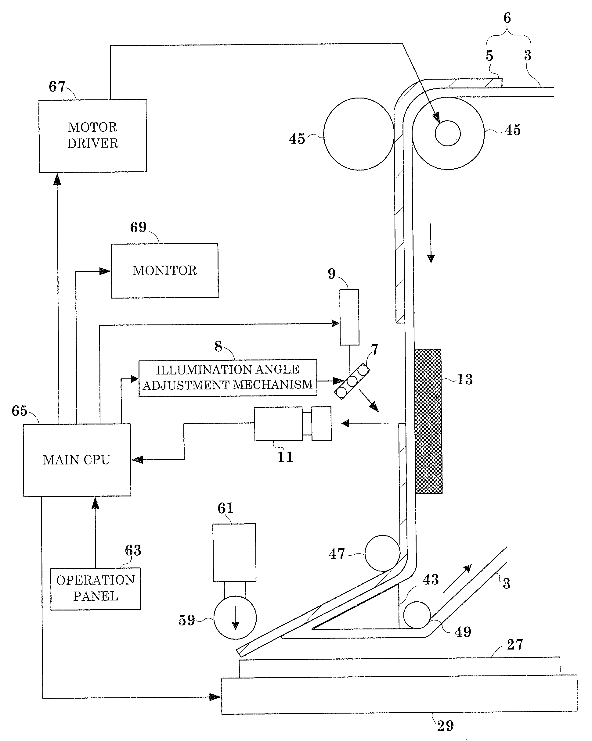
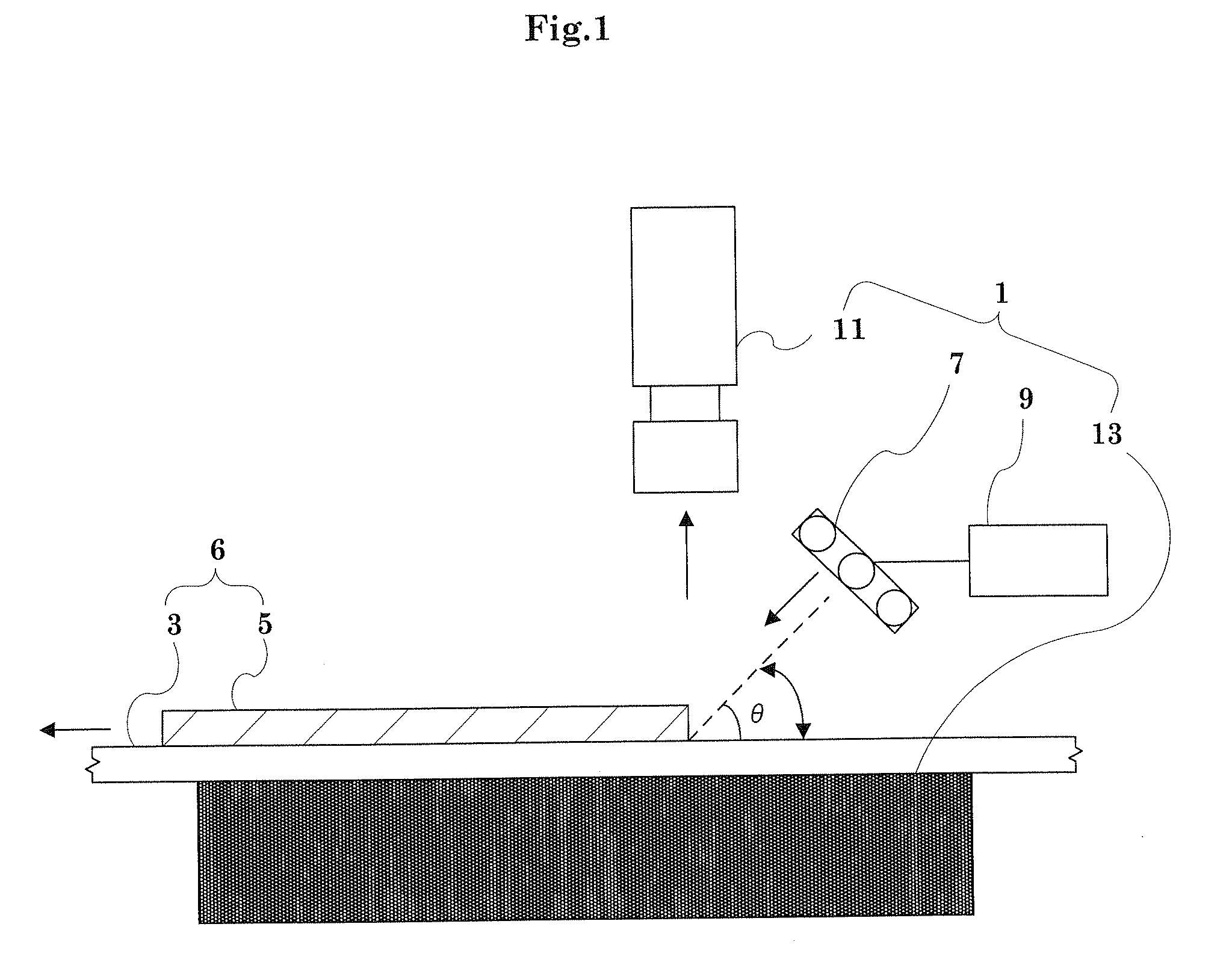
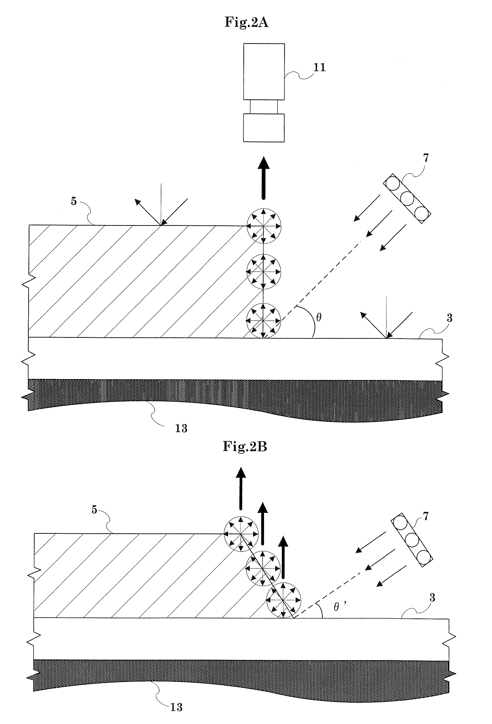
[0049]As shown in FIG. 1, an adhesive film position detector 1 includes an illuminator 7, a dimmer 9, an illumination angle adjustment mechanism 8 (see FIG. 7) and a CCD camera 11. Herein, the illuminator 7 emits light to a rear end of an adhesive film 5 joined to a base film 3 which is fed leftward in FIG. 1. The dimmer 9 adjusts chromaticity and illuminance of the light emitted from the illuminator 7. The illumination angle adjustment mechanism 8 adjusts an illumination angle of the light emitted from the illuminator 7. The CCD camera 11 captures an image of the light which is emitted from the illuminator 7, is reflected irregularly at ...


PUM

PropertyMeasurementUnit
Transparencyaaaaaaaaaa
Wavelengthaaaaaaaaaa

Abstract

An illuminator emits light obliquely to an end of an adhesive film. A CCD camera is provided in a direction perpendicular to the adhesive film to capture an image of the light reflected irregularly from the end of the adhesive film. A black plate is provided on a back side of the adhesive film. In the image obtained by the CCD camera, therefore, only the end of the adhesive film is displayed whitely in a line shape. A position of the adhesive film is determined based on a line corresponding to the end of the adhesive film. Since the light reflected from the end of the adhesive film is utilized, the position of the adhesive film can be determined accurately irrespective of a color of the adhesive film, a color of a base film to which the adhesive film is joined, and a depth of each color.

Description

BACKGROUND OF THE INVENTION[0001](1) Field of the Invention[0002]The present invention relates to an adhesive film position detector and an adhesive film joining apparatus. Specifically, in one step of surface treatment for various substrates such as a semiconductor substrate and a glass substrate for use in a liquid crystal display device, the adhesive film position detector is used when an adhesive film is joined to a surface of a substrate. Herein, the adhesive film has a shape corresponding to a shape of the substrate.[0003](2) Description of the Related Art[0004]Conventionally, there have been proposed various adhesive film joining apparatuses for joining, to a surface of a substrate, an adhesive film having a shape corresponding to a shape of the substrate. For example, JP 07-195527 A discloses an adhesive film joining apparatus having the following configuration. That is, a colored adhesive film joined to a transparent base tape is fed by film feed means, and then is detected...

Claims


Application Information

Patent Timeline
IPC IPC(8): B65H19/18
CPCB32B38/1841B32B2457/14G02B27/62G01B11/02G01B11/028B32B2457/202
Inventor YAMAMOTO, MASAYUKIIKEDA, SATOSHI
Owner NITTO DENKO CORP
Why Eureka
Try Eureka