Control Method and Controller for Pwm Cyclo-Converter

Inactive Publication Date: 2008-11-27
YASKAWA DENKI KK
View PDF1 Cites 11 Cited by
  • Summary
  • Abstract
  • Description
  • Claims
  • Application Information

AI Technical Summary

Benefits of technology

[0112]According to the present invention, since a switching loss the same as that of a two-phase modulation and a voltage accuracy the same as that of a three-phase

Problems solved by technology

However, since a dc capacitor is not present in the PWM cyclo-converter as in a

Method used


Image

  • Control Method and Controller for Pwm Cyclo-Converter
  • Control Method and Controller for Pwm Cyclo-Converter
  • Control Method and Controller for Pwm Cyclo-Converter

Examples


Example

First Embodiment stages indicate Vmax, Vmid and Vmin respectively designated by Emax, Emid and Emin and lower stages respectively designate line voltages dVmax=max−Vmin, dVmid1=Vmax−Vmid and dVmid2=Vmid−Vmin.

[0133]In the voltage waveforms shown in FIG. 7(b), in the sections, a reference input potential Ebase outputs the voltage wave form when Emin=Ebase. Switching times 1 to 9 in FIG. 7(b) can be expressed as in Table 2. The numbers of formulas in the Table are identical with the numbers of formulas described in claims.

TABLE 2SectionFormulaSetting time of timer1, 9(1)EmaxTs(Vmid-Vmin)2{Emax(Emax-Emid)-Emin(Emid-Emin)}2, 8(2)EmaxTs(Vmax-Vmid)2{Emax(Emax-Emid)-Emin(Emid-Emin)}3, 7(3)Ts2(1-(Emax-Emin)(Vmax-Vmin){Emax(Emax-Emid)-Emin(Emid-Emin)})4, 6(4)-EminTs(Vmid-Vmin)2{Emax(Emax-Emid)-Emin(Emid-Emin)}5(5)-EminTs(Vmax-Vmid){Emax(Emax-Emid)-Emin(Emid-Emin)}

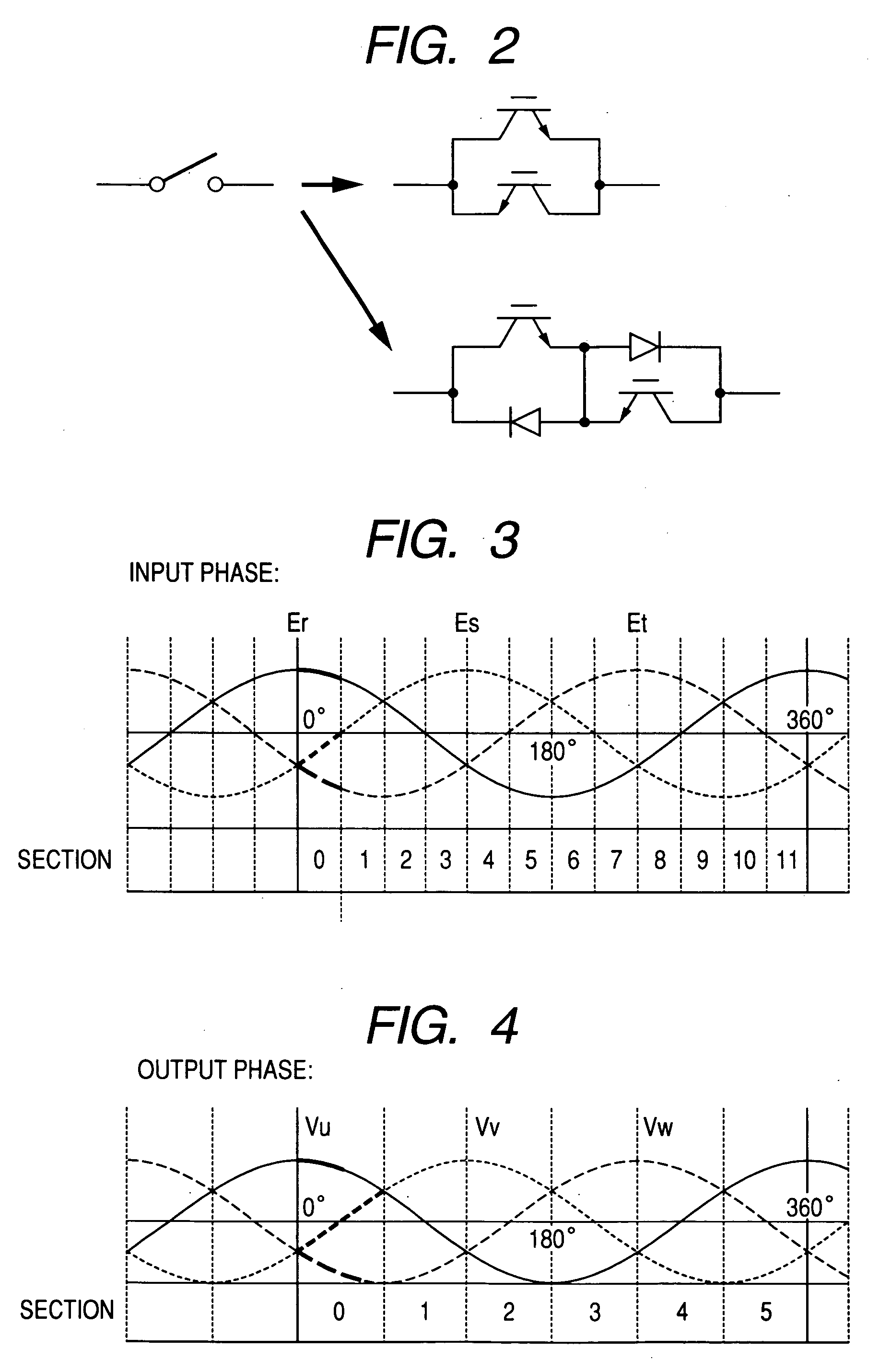
[0134]In the case of the input section of “0” in FIG. 3 and the output section “0” in FIG. 4 and in the case of the input section o...


PUM


Abstract

A control method for a PWM cyclo-converter is provided in which a voltage can be accurately generated even when a voltage command is small.
In the PWM cyclo-converter, the turning on and off operations of two-way semiconductor switch are repeated at intervals of short time. As switching patterns, within the intervals of short time, a first terminal of output side terminals outputs in order a maximum potential phase P, an intermediate potential phase M and the maximum potential phase N, a second terminal of the output side terminals outputs in order the maximum potential phase P, the intermediate potential phase M, a minimum potential phase N, the intermediate potential phase M and the maximum potential phase P, and a third terminal of the output side terminals outputs in order the intermediate potential phase M, the minimum potential phase N and the intermediate potential phase M.

Description

TECHNICAL FIELD[0001]The present invention relates to a power converter that can convert an output from an ac power source to an arbitrary frequency and more particularly to a PWM cyclo-converter using a pulse width modulation (PWM) control system.RELATED ART[0002]Since in the PWM cyclo-converter, an ac power source is directly connected to a load side by a semiconductor element for a power, the voltage of an output and the current of an input can be controlled at the same time. However, since a dc capacitor is not present in the PWM cyclo-converter as in a PWM inverter, the voltage not lower than an input voltage cannot be outputted. Accordingly, a two-phase modulation high in its voltage use rate is ordinarily used (for instance, see Patent Document 1).[0003]FIG. 10 is a diagram showing a wave form of input phase information of a “controller for three phase / three phase PWM cyclo-converter”. The diagram shows wave forms of input current commands ir, is and it of three phases r, s a...

Claims


Application Information

Patent Timeline
IPC IPC(8): H02M5/297H02M3/335
CPCH02M3/33507H02M5/297
Inventor YAMAMOTO, EIJIHARA, HIDENORIKANG, JUN-KOO
Owner YASKAWA DENKI KK
Why Eureka
Try Eureka