Seam welding warpage prevention method and apparatus

Active Publication Date: 2012-03-29
HONDA MOTOR CO LTD
View PDF4 Cites 12 Cited by
  • Summary
  • Abstract
  • Description
  • Claims
  • Application Information

AI Technical Summary

Benefits of technology

[0015]According to the present invention, it is possible to obtain the same effect as described above.
[0016]According to the present invention, it is possible to apply an external force o

Problems solved by technology

However, the seam welding may cause the workpieces to warp in a longitudinal direction thereof due to cooling contraction immediately after the welding if the workpieces are not uniform in thermal contraction.
Even if the workpieces are of the same material, in a case in which the workpieces are made different in thickness from each other, thermal contraction thereof becomes non-uniform.

Method used


Image

  • Seam welding warpage prevention method and apparatus
  • Seam welding warpage prevention method and apparatus
  • Seam welding warpage prevention method and apparatus

Examples


first embodiment

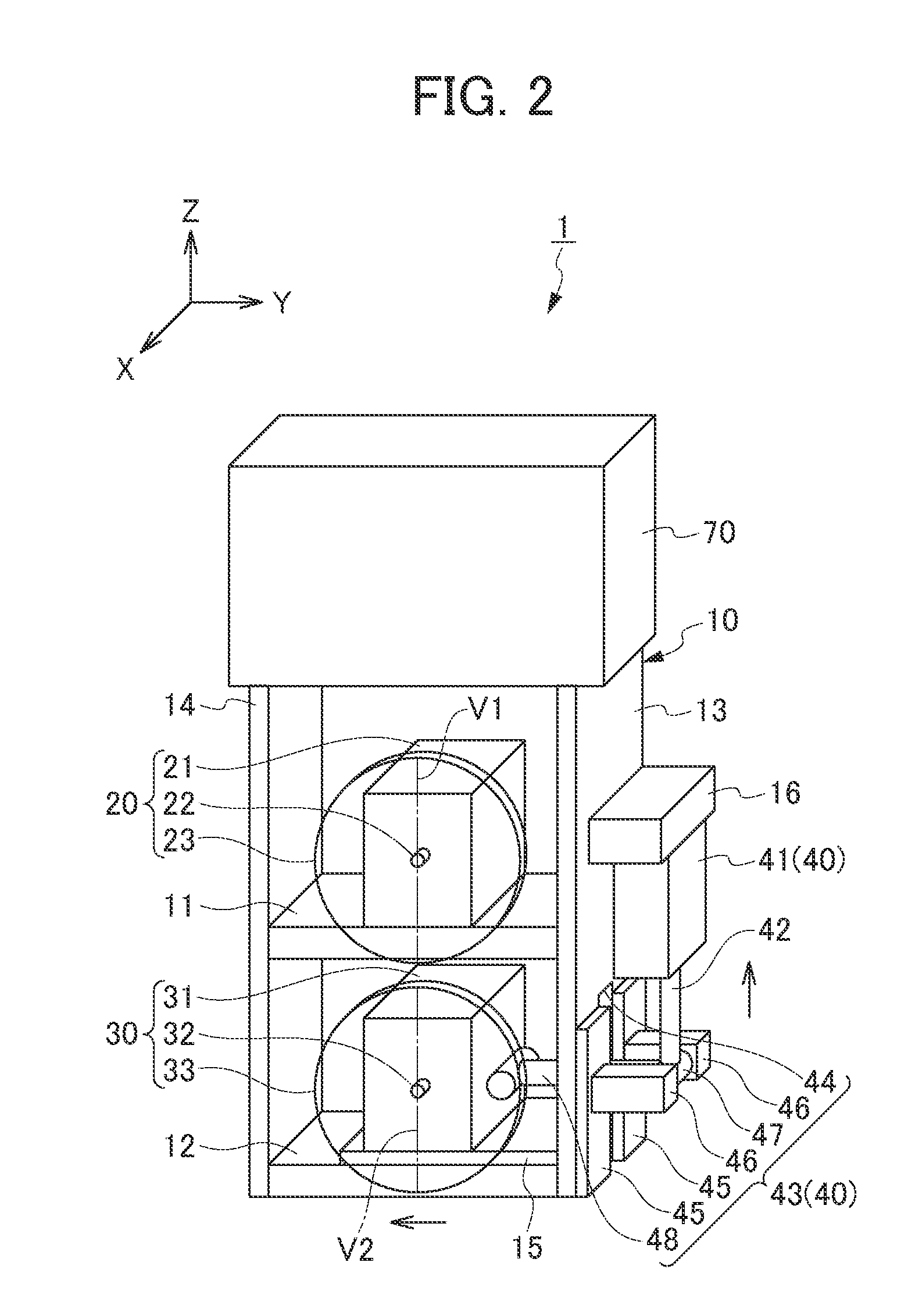
[0044]FIGS. 2 and 3 are schematic perspective views showing a seam welding warpage prevention apparatus 1 according to a first embodiment of the present invention.

[0045]The seam welding warpage prevention apparatus 1 is provided with a chassis 10, a pair of welding electrodes 20 and 30 supported by the chassis 10, an offset mechanism 40, and a transformer 70.

[0046]The chassis 10 is provided so that the welding electrodes 20 and 30, the offset mechanism 40 and the transformer 70 are mounted in a predetermined positional relationship. For convenience, in FIGS. 2 and 3, it is assumed that the arrow X is directed in a forward direction from the back of the chassis 10, the arrow Y is directed in a rightward direction from the left of the chassis 10, and the direction of the arrow Z is directed in an upward direction from the bottom of the chassis 10.

[0047]More specifically, the chassis 10 includes an upper mounting unit 11 to mount the welding electrode 20, a lower mounting unit 12 to mo...

second embodiment

[0089]FIG. 4 is a schematic perspective view showing a seam welding warpage prevention apparatus 2 according to a second embodiment of the present invention.

[0090]The seam welding warpage prevention apparatus 2 is provided with a chassis 10, a pair of welding electrodes 20 and 30 supported by the chassis 10, an offset mechanism 50, and a transformer 70.

[0091]Since, constituent elements of the seam welding warpage prevention apparatus 2 according to the second embodiment are the same as those of the seam welding warpage prevention apparatus 1 according to the first embodiment except for the offset mechanism 50, descriptions of the same constituent elements are omitted.

[0092]As the offset mechanism 50, for example, a small sized actuator 51 is mounted between the side plate 13 of the chassis 10 and a side portion of the electrode holding unit 31 of the lower welding electrode 30. The actuator extends when current is applied and returns to its original state when no current is applied....

third embodiment

[0096]FIG. 5 is a schematic perspective view showing a seam welding warpage prevention apparatus 3 according to a third embodiment of the present invention.

[0097]The seam welding warpage prevention apparatus 3 is provided with a chassis 10, a pair of welding electrodes 20 and 30 supported by the chassis 10, an offset mechanism 60, and a transformer 70.

[0098]Since, constituent elements of the seam welding warpage prevention apparatus 3 according to the third embodiment are the same as those of the seam welding warpage prevention apparatus 1 according to the first embodiment except for the offset mechanism 60, descriptions of the same constituent elements are omitted.

[0099]The offset mechanism 60 includes a motor 61. The motor 61 includes a rod 62 extending through a through hole 63 formed on the side plate 13 of the chassis 10. The end portion of the rod 62 is attached to the side portion of the electrode holding unit 31.

[0100]When the motor 61 is driven in one direction, the rod 62 ...


PUM

PropertyMeasurementUnit
Contraction enthalpyaaaaaaaaaa

Abstract

It is an object of the present invention to provide a seam welding warpage prevention method and apparatus capable of preventing warpage caused by cooling contraction after welding, in a case where workpieces are different from one another in material and thickness, and thus not uniform in thermal contraction. In the seam welding warpage prevention method for welding a plurality of workpieces W1 and W2 that are not uniform in thermal contraction with respect to an energizing direction, the workpieces W1 and W2 are clamped with a pair of roller electrodes 23 and 33 while applying current. The welding is performed in a state where the roller electrode 33 that abuts on the workpiece W2 having higher thermal contraction is offset in an advancing direction ahead of the roller electrode 23 that abuts on the workpiece W1 having lower thermal contraction.

Description

[0001]This application is based on and claims the benefit of priority from Japanese Patent Application No. 2010-215480, filed on 27 Sep. 2010, the content of which is incorporated herein by reference.BACKGROUND OF THE INVENTION[0002]1. Field of the Invention[0003]The present invention relates to a seam welding warpage prevention method and apparatus. More particularly the present invention relates to a seam welding warpage prevention method and apparatus for welding a plurality of members to be welded that are not uniform in thermal contraction with respect to an energization direction.[0004]2. Related Art[0005]Conventionally, there is known a technique of seam welding that clamps two or more workpieces (members to be welded) by roller electrodes and moves the roller electrodes while applying pressure and current to the workpieces, so as to continuously weld the workpieces.SUMMARY OF THE INVENTION[0006]However, the seam welding may cause the workpieces to warp in a longitudinal dire...

Claims


Application Information

Patent Timeline
IPC IPC(8): B23K11/08
CPCB23K11/061B23K11/08B23K2203/18B23K11/20B23K2203/04B23K11/16B23K11/06B23K2103/04B23K2103/18
Inventor HASEGAWA, EISAKUKANEKO, MITSUGUIKEDA, TAKAFUMIKOBAYASHI, HARUHIKO
Owner HONDA MOTOR CO LTD
Why Eureka
Try Eureka