Integrated aircraft interior

a fully integrated, aircraft interior technology, applied in the field of aircraft interiors, can solve the problems of significant undesirable weight to the overall weight of the aircraft, and achieve the effect of reducing the amount of labor and parts required

Inactive Publication Date: 2012-03-29
BE INTPROP
View PDF9 Cites 52 Cited by
  • Summary
  • Abstract
  • Description
  • Claims
  • Application Information

AI Technical Summary

Benefits of technology

[0007]Briefly, and in general terms, the present invention provides for an integrated aircraft interior “floor to floor” solution to the need for a fully integrated commercial aircraft interior module suitable for installation to existing aircraft structural supports, including the sidewall linings, decompression ventilation provisions, overhead stowage compartments (OHSC), cabin air distribution ducting, personal service units (PSU) and ceilings. These components are designed, fabricated, and fully pre-assembled to reduce the labor hours and parts required during installation process into the aircraft. The sidewall linings, overhead stowage compartments and other interior structure integrated items attach to existing aircraft structural provisions.

Problems solved by technology

Commercial aircraft interior sidewall linings, decompression ventilation provisions, overhead stowage compartments, cabin air distribution ducting, personal service units (PSU) and ceilings have traditionally been designed as individual components, with other functional components, such as air conditioning ducting components and lighting components secured to them by additional mounting brackets that, taken together for the entire aircraft, can contribute significant undesirable weight to the overall weight of the aircraft.

Method used


Image

  • Integrated aircraft interior
  • Integrated aircraft interior
  • Integrated aircraft interior

Examples


first embodiment

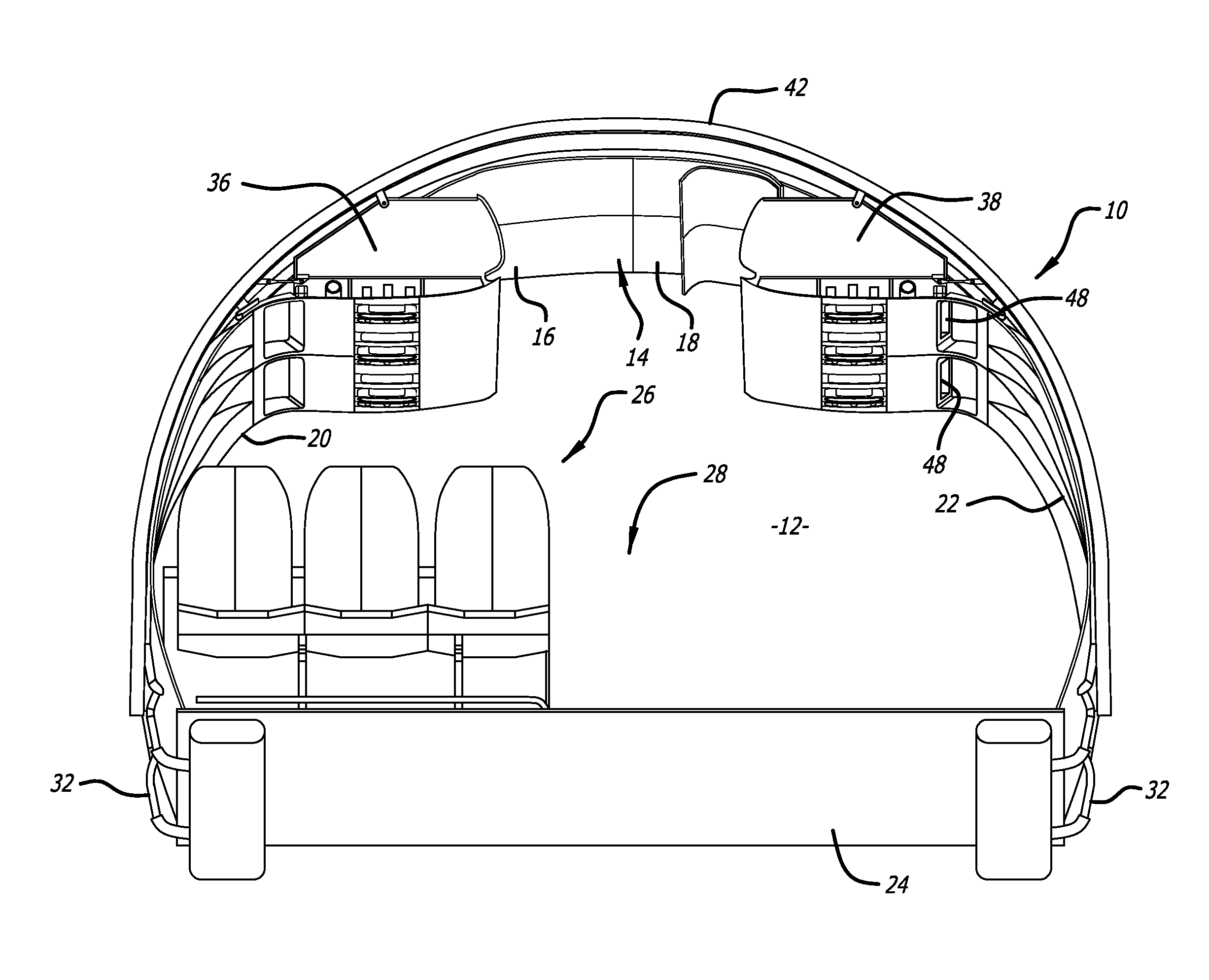
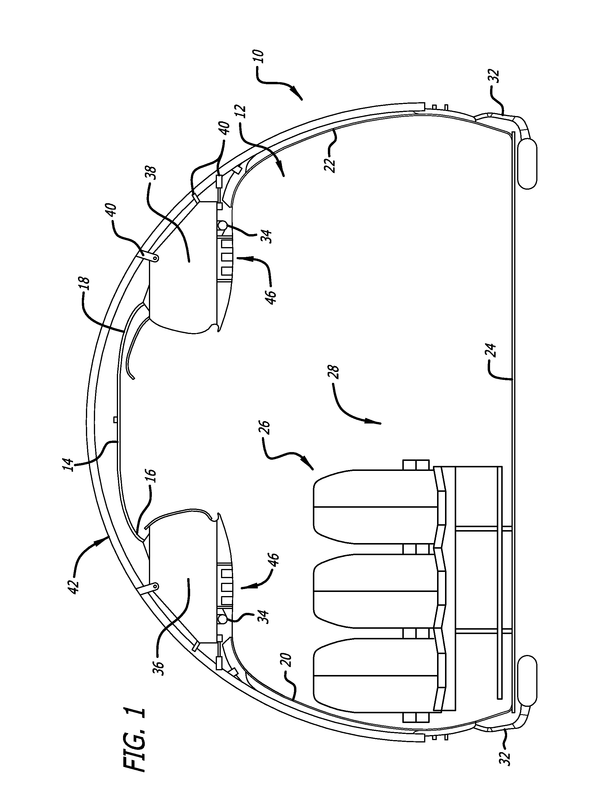
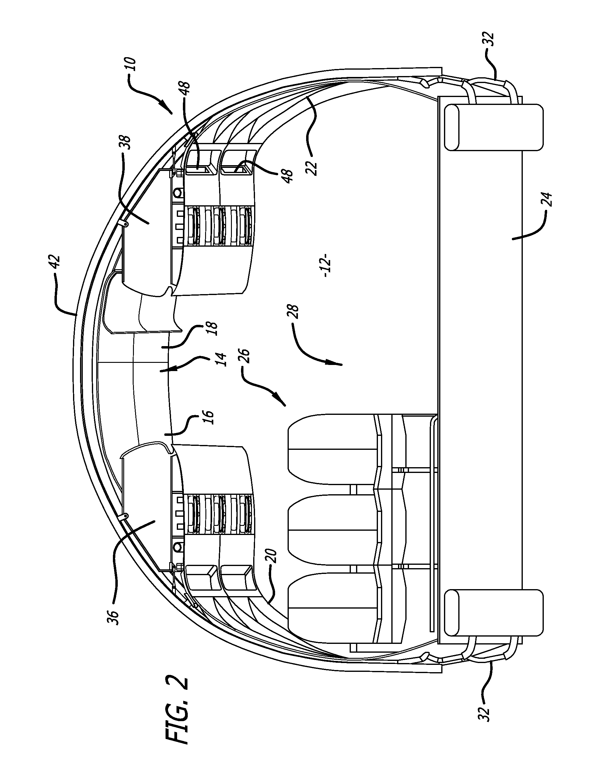
[0028]Referring to FIGS. 1-10, in a first embodiment, the present invention provides for a “floor to floor” integrated aircraft interior module 10 for an interior cabin area 12 of a passenger aircraft (not shown). As is illustrated in FIGS. 1 and 2, the aircraft passenger cabin area typically includes an overhead ceiling portion 14 including at least one ceiling panel, with a first or right side 16 and a second or left side 18, a first or right sidewall lining portion 20, a second or left sidewall lining portion 22, and a floor 24 with at least one set of passenger seats 26, and typically an aisle 28 between first and second sets of passenger seats. The sidewall lining portions each preferably also include one or more decompression ventilation panels or vents 30, and cabin air distribution ducting 32, including risers 33 and plenums 35, connected to gasper air distribution ducting 34 for ventilation in the interior cabin area, as is illustrated in FIGS. 3-10.

[0029]The aircraft passe...

second embodiment

[0031]Referring to FIGS. 11-17, in a second embodiment, the present invention provides for a “floor to floor” integrated aircraft interior module 110 for an aircraft passenger cabin area 112 of a passenger aircraft (not shown). As is illustrated in FIGS. 11 and 13, the aircraft passenger cabin area typically includes an overhead ceiling portion 114 including at least one ceiling panel, with a first or right side 116 and a second or left side 118, a first or right sidewall lining portion 120, a second or left sidewall lining portion 122, and a floor 124 with at least one set of passenger seats 126, and typically an aisle 128 between first and second sets of passenger seats. One or both of the sidewall lining portions preferably also include one or more decompression ventilation panels or vents 130, and cabin air distribution ducting 132, including risers 133 and plenums 135, connected to gasper air distribution ducts 134 for ventilation in the interior cabin area, as illustrated in F...


PUM


Abstract

An integrated aircraft interior module includes one or more ceiling panels, sidewall linings, decompression ventilation provisions, and overhead stowage compartments including cabin air distribution ducting, personal service units. The sidewall linings, overhead stowage compartments and other interior structure integrated items attach to existing aircraft structural provisions.

Description

CROSS-REFERENCES TO RELATED APPLICATIONS[0001]This application is based upon and claims priority from U.S. Provisional Application No. 61 / 385,954, filed Sep. 23, 2010 incorporated by reference in its entirety.BACKGROUND[0002]The present invention relates generally to aircraft interiors, and more particularly relates to a fully integrated commercial aircraft interior module including sidewall linings, decompression ventilation provisions, overhead stowage compartments, cabin air distribution ducting, personal service units (PSU) and ceilings, all configured to attach as an integrated interior module suitable for installation to existing aircraft structural supports, and suitable for retrofitting of commercial aircraft interiors.[0003]Overhead stowage bins are currently generally shelf or fixed overhead stowage bins, pivot overhead stowage bins, or translating bins overhead stowage bins. The shelf or fixed bin is currently the most common design, having a door that typically opens out...

Claims


Application Information

Patent Timeline
Patent Type & Authority Applications(United States)
IPC IPC(8): B64D11/00
CPCB64C1/066Y02T50/46B64D2011/0046B64D11/003B64C2001/009Y02T50/40
Inventor PAPKE, ROBERTLUNDBERG, ANDREW J.BANFIELD, WILLIAM J.
Owner BE INTPROP
Why Eureka
Try Eureka