Switch-Mode Voltage Regulator

a voltage regulator and switchmode technology, applied in the direction of electric variable regulation, power conversion systems, instruments, etc., can solve the problem of severe constraints on the level of disturbances on the supply

Inactive Publication Date: 2012-03-29
ST ERICSSON SA
View PDF4 Cites 85 Cited by
  • Summary
  • Abstract
  • Description
  • Claims
  • Application Information

AI Technical Summary

Benefits of technology

[0008]For the above reasons, it is desirable to make a DC-DC converter able to pass smoothly between buck and b

Problems solved by technology

Because the electronics receiving the regulated supply is sensitive, severe constraints are pl

Method used


Image

  • Switch-Mode Voltage Regulator
  • Switch-Mode Voltage Regulator
  • Switch-Mode Voltage Regulator

Examples


Embodiment Construction

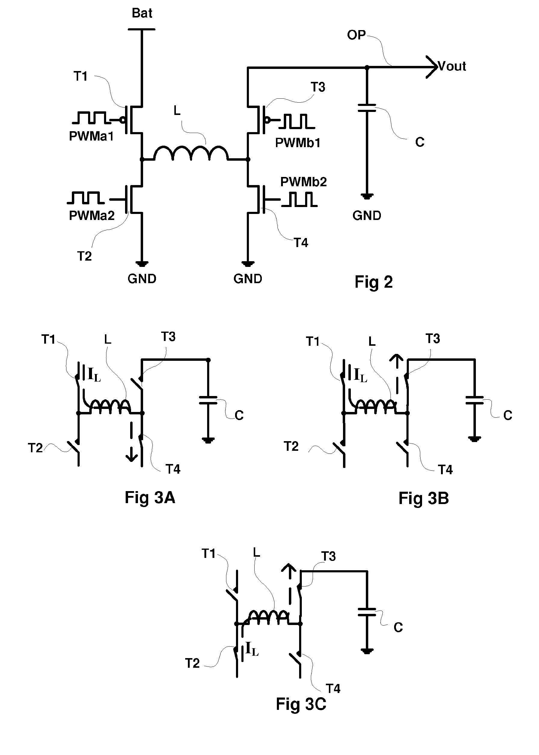
[0046]Same references designate same elements in the different figures. Furthermore, only the elements which are useful to understanding are represented and disclosed. Especially the circuits downstream of the DC-DC converter are not detailed, these circuits being compatible with any usual use of a regulated voltage.

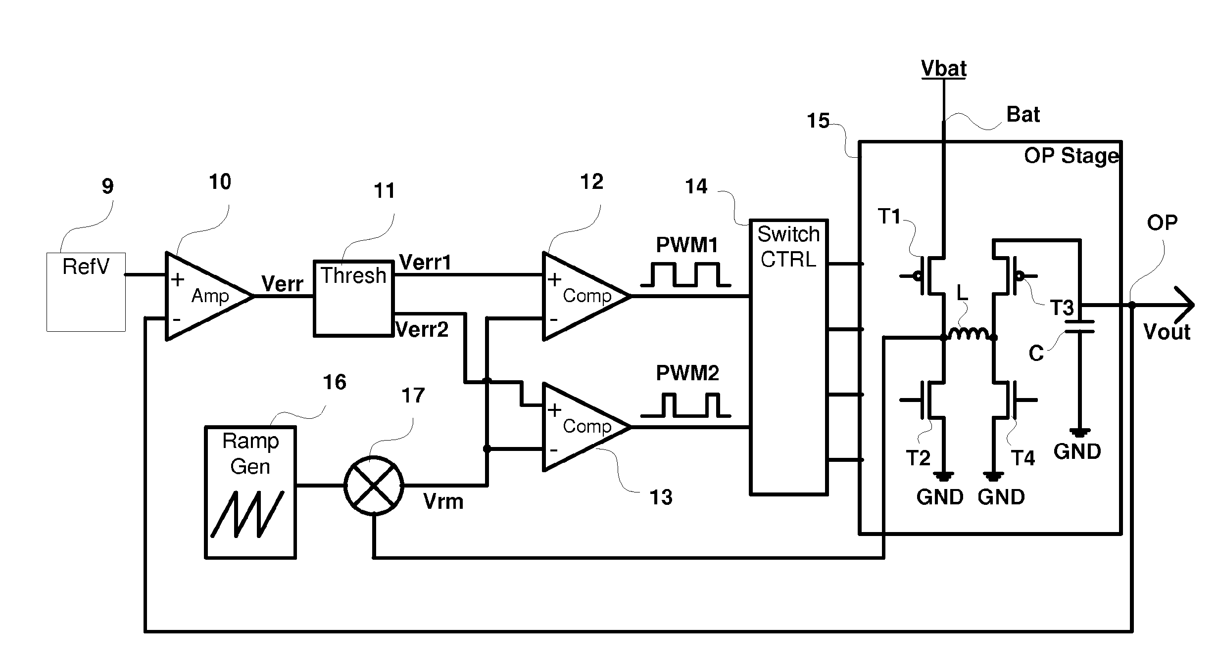
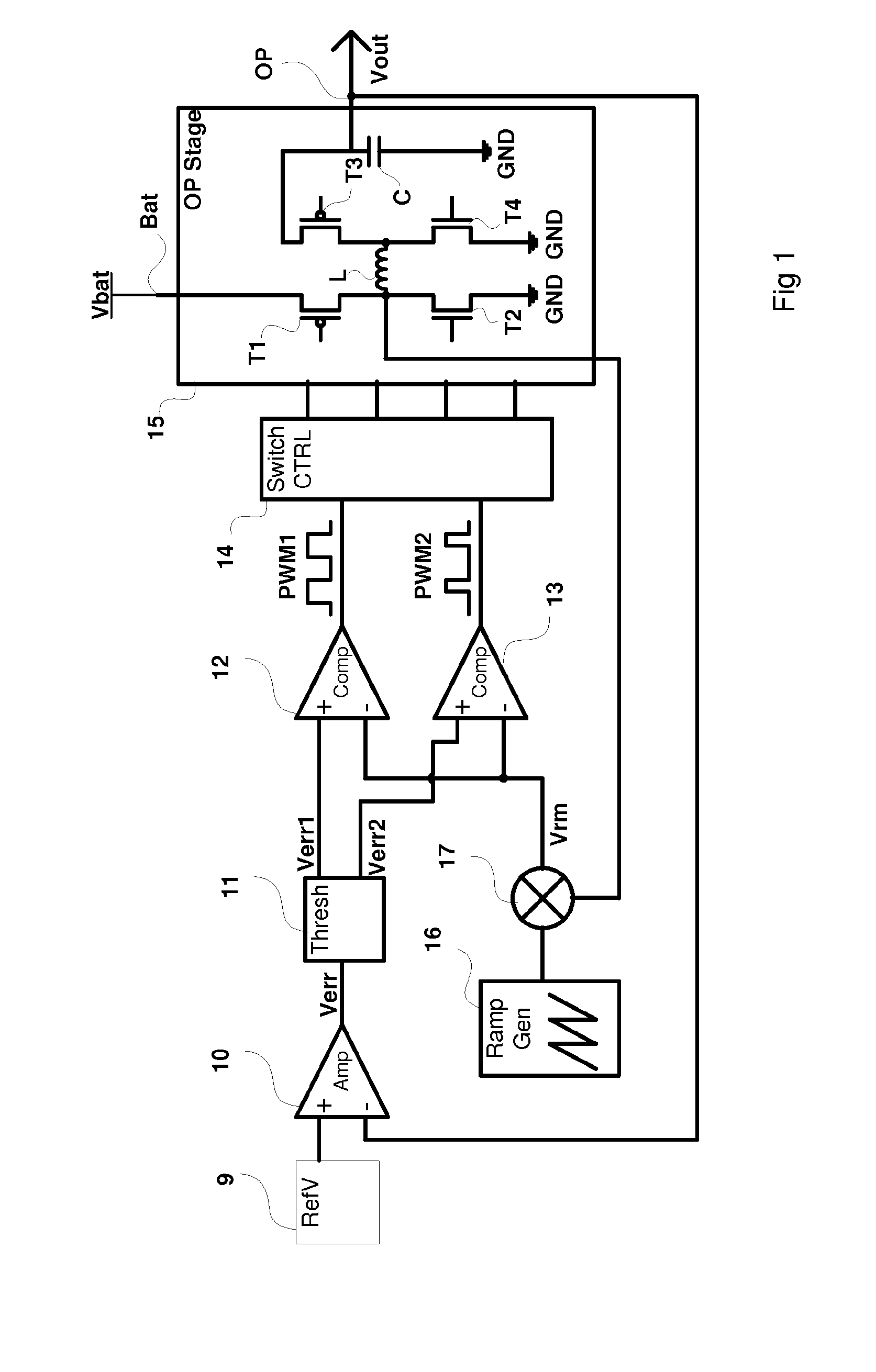
[0047]FIG. 1 represents an embodiment of a buck-boost converter, able to pass between buck and boost modes without interruption of the regulated supply.

[0048]An error amplifier 10 (Amp) receives a reference voltage from a reference voltage source 9 (RefV) at its non-inverting input. Error amplifier 10 has its inverting input coupled to output OP of the buck-boost converter. The error signal Verr output by error amplifier 10 is provided to a threshold generator 11 (Thresh) which supplies a first derived error signal Verr1 to a first comparator 12 (Comp) and a second derived error signal Verr2, offset from derived error signal Verr1, to a second comparator 13. Derived erro...


PUM


Abstract

The invention concerns a switch-mode voltage regulator, comprising : an inductor (L); a generator for producing a voltage ramp (16); circuitry (12, 13) for producing at least one pulse stream from said voltage ramp; switch control circuitry (14) for controlling switching of a current in the inductor according to said pulse stream; and a first control loop adapted to modulate the form of the voltage ramp according to the current flowing in the inductor.

Description

FIELD OF THE INVENTION[0001]The present invention concerns switch-mode power supplies (DC-DC converters), in particular those in integrated circuit form capable of providing a regulated output power supply both below and above the unregulated input power supply. Such DC-DC converters are commonly known as buck-boost converters or step UP / DOWN DC / DC converters.BACKGROUND OF THE INVENTION[0002]Switched mode power supplies are widely used in battery powered equipment to convert an unregulated supply from the battery voltage into a regulated supply for other electronic circuits which are highly sensitive to power supply stability.[0003]The voltage supplied by batteries varies significantly as a function of the level of charge remaining. Therefore, the wider the range of voltage the electronic circuits can function over, the longer the equipment can be used between changing or charging the battery. For example, it is common for the voltage supplied by the battery in a mobile battery powe...

Claims


Application Information

Patent Timeline
IPC IPC(8): G05F1/46
CPCH02M3/1582
Inventor TROCHUT, SEVERIN
Owner ST ERICSSON SA
Why Eureka
Try Eureka