Switch Mode Regulators

A technology of switching mode and voltage regulator, which is applied in the direction of instruments, regulating electric variables, output power conversion devices, etc.

Active Publication Date: 2011-11-30
ST ERICSSON SA
View PDF7 Cites 16 Cited by
  • Summary
  • Abstract
  • Description
  • Claims
  • Application Information

AI Technical Summary

Problems solved by technology

Because the electronic circuits receiving the regulated power supply are very sensitive, there are strict restrictions on the level of disturbance (such as ripple or spike) that the voltage can tolerate

Method used


Image

  • Switch Mode Regulators
  • Switch Mode Regulators
  • Switch Mode Regulators

Examples


Embodiment Construction

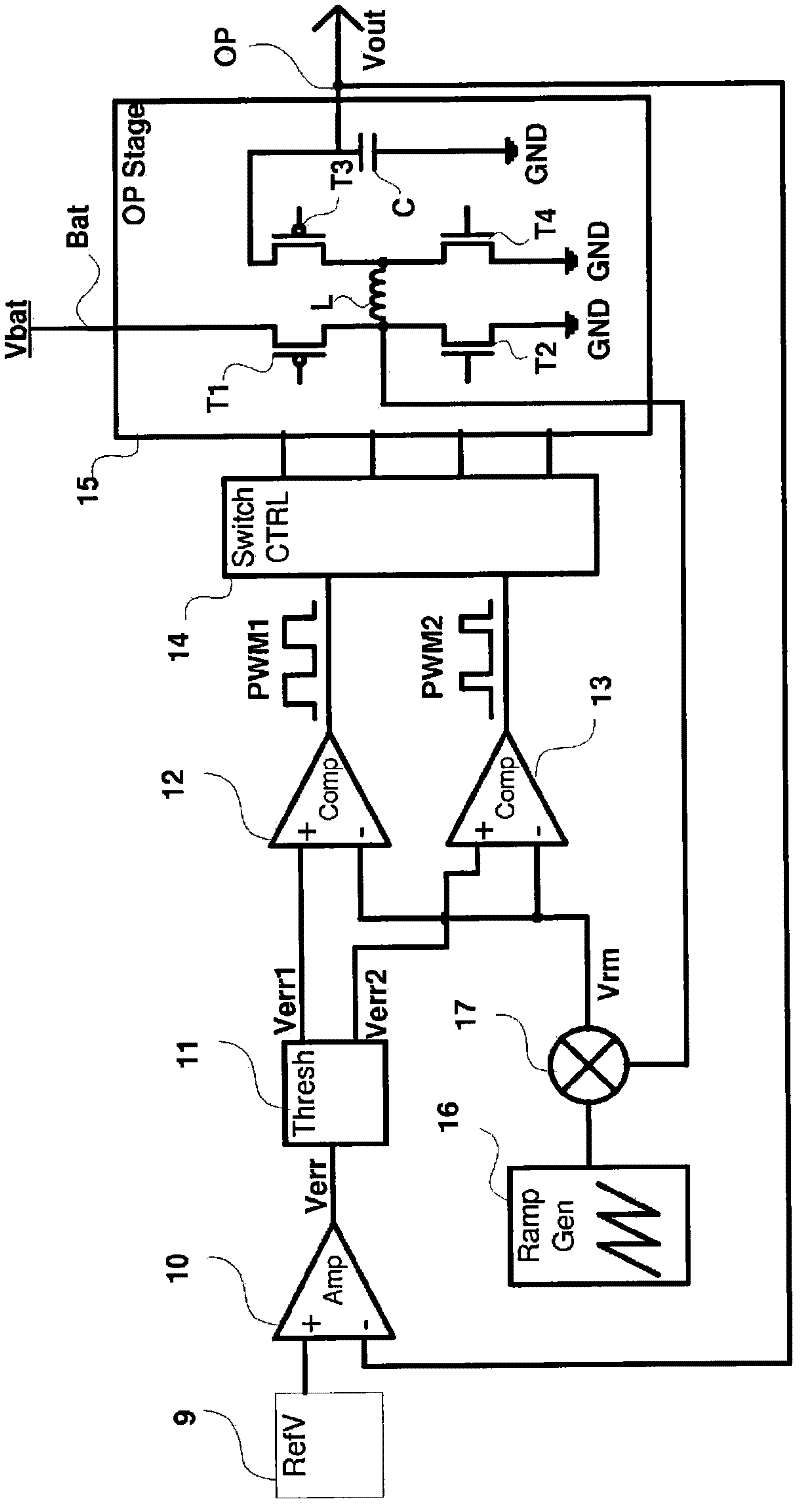
[0046] The same reference numerals designate the same elements in different drawings. In addition, only elements useful for understanding are shown and disclosed. In particular, the downstream circuits of the DC-DC converter are not shown in detail, which are equivalent to any usual use of a regulated voltage.

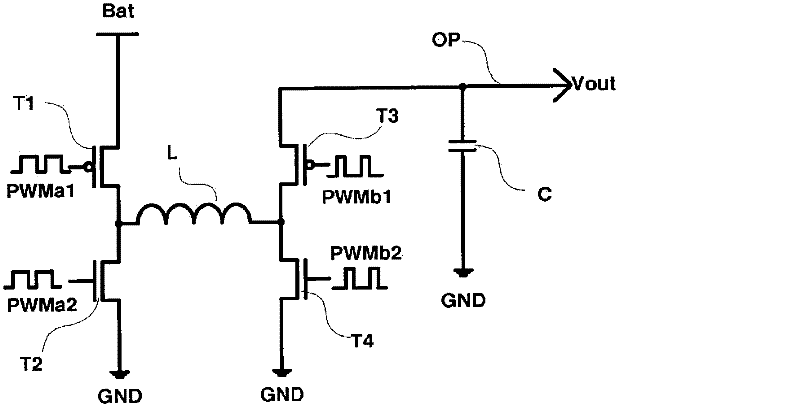
[0047] figure 1 One embodiment of a buck-boost converter capable of transitioning between buck and boost modes without interruption of a regulated power supply is shown.

[0048] The error amplifier 10 (Amp) receives a reference voltage at its inverting input from a reference voltage source 9 (RefV). The inverting input terminal of the error amplifier 10 is coupled to the output terminal OP of the buck-boost converter. The error signal Verr output by the error amplifier 10 is supplied to a threshold generator 11 (Thresh), which supplies a first derived error signal Verr1 to a first comparator 12 (Comp) and a second derived error signal offset from the derived error ...


PUM


Abstract

The invention concerns a switch-mode voltage regulator, comprising : an inductor (L); a generator for producing a voltage ramp (16); circuitry (12, 13) for producing at least one pulse stream from said voltage ramp; switch control circuitry (14) for controlling switching of a current in the inductor according to said pulse stream; and a first control loop adapted to modulate the form of the voltage ramp according to the current flowing in the inductor.

Description

technical field [0001] The present invention relates to switched mode power supplies (DC-DC converters), especially in the form of integrated circuits capable of providing regulated output power both above and below an unregulated input supply. Such DC-DC converters are generally known as buck-boost converters or step UP / DOWN DC-DC converters. Background technique [0002] Switch-mode power supplies are widely used in battery-operated equipment to convert unregulated power from the battery voltage to regulated power for other electronic circuits that are highly sensitive to power stability. [0003] The voltage supplied by the battery pack varies significantly depending on the level of remaining charge. Therefore, the wider the voltage range over which the electronic circuit can operate, the longer the device can be used between changing or charging the battery. For example, the voltage supplied by a battery in a mobile battery powered device is typically allowed to drop f...

Claims


Application Information

Patent Timeline
Patent Type & Authority Applications(China)
IPC IPC(8): G05F1/575H02M3/158
CPCH02M3/1582
Inventor 塞韦林·特罗许特
Owner ST ERICSSON SA
Why Eureka
Try Eureka