Apparatus and method utilizing high power density electron beam for generating pulsed stream of ablation plasma

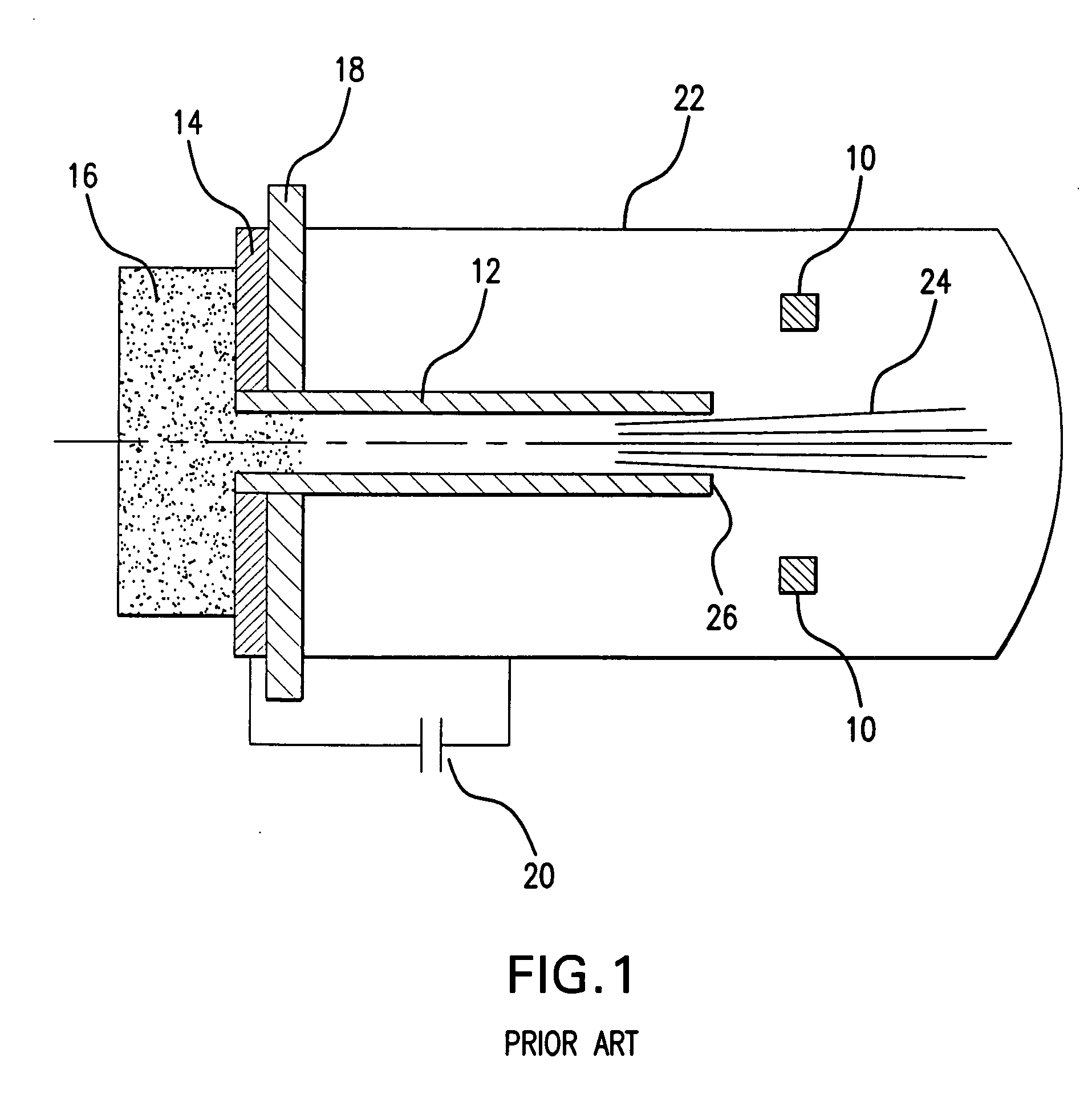
a high-power density electron beam and plasma technology, applied in the field of plasma generation, can solve the problems of limited beam current and electron beam power, and the device shown in fig. 1 is somewhat deficient in its ability to deliver the electron beam of superior electron current density

Active Publication Date: 2007-02-01
NEOCERA
View PDF4 Cites 19 Cited by
  • Summary
  • Abstract
  • Description
  • Claims
  • Application Information

AI Technical Summary

Benefits of technology

[0027] Generating a cathode plasma at a cathode member with the cathode plasma having a cathode plasma front layer, and emitting an electron beam from the front layer of the cathode plasma. Further the method includes supplying a process gas into the processing chamber in the vicinity of the anode member thereby creating a zone of an increased gas pressure and concentration. The electron beam is directed towards the anode member, thereby initiating ionization of the process gas in the vicinity of the anode member forming an anode plasma having an anode plasma front layer and increasing the power of the electron beam once the anode and cathode plasma front layers interact with each other at a double contact layer defined therebetween.

Problems solved by technology

However, since the boundary of the plasma is the source of the electron beam, the beam current and the power of the electron beams are limited in part by the ability of plasma in the plasma source to supply electrons to its boundary, e.g. are limited by the concentration of the plasma.
The device shown in FIG. 1 is thus somewhat deficient in its ability to deliver the electron beams of superior electron current density.

Method used


Image

  • Apparatus and method utilizing high power density electron beam for generating pulsed stream of ablation plasma
  • Apparatus and method utilizing high power density electron beam for generating pulsed stream of ablation plasma
  • Apparatus and method utilizing high power density electron beam for generating pulsed stream of ablation plasma

Examples


Embodiment Construction

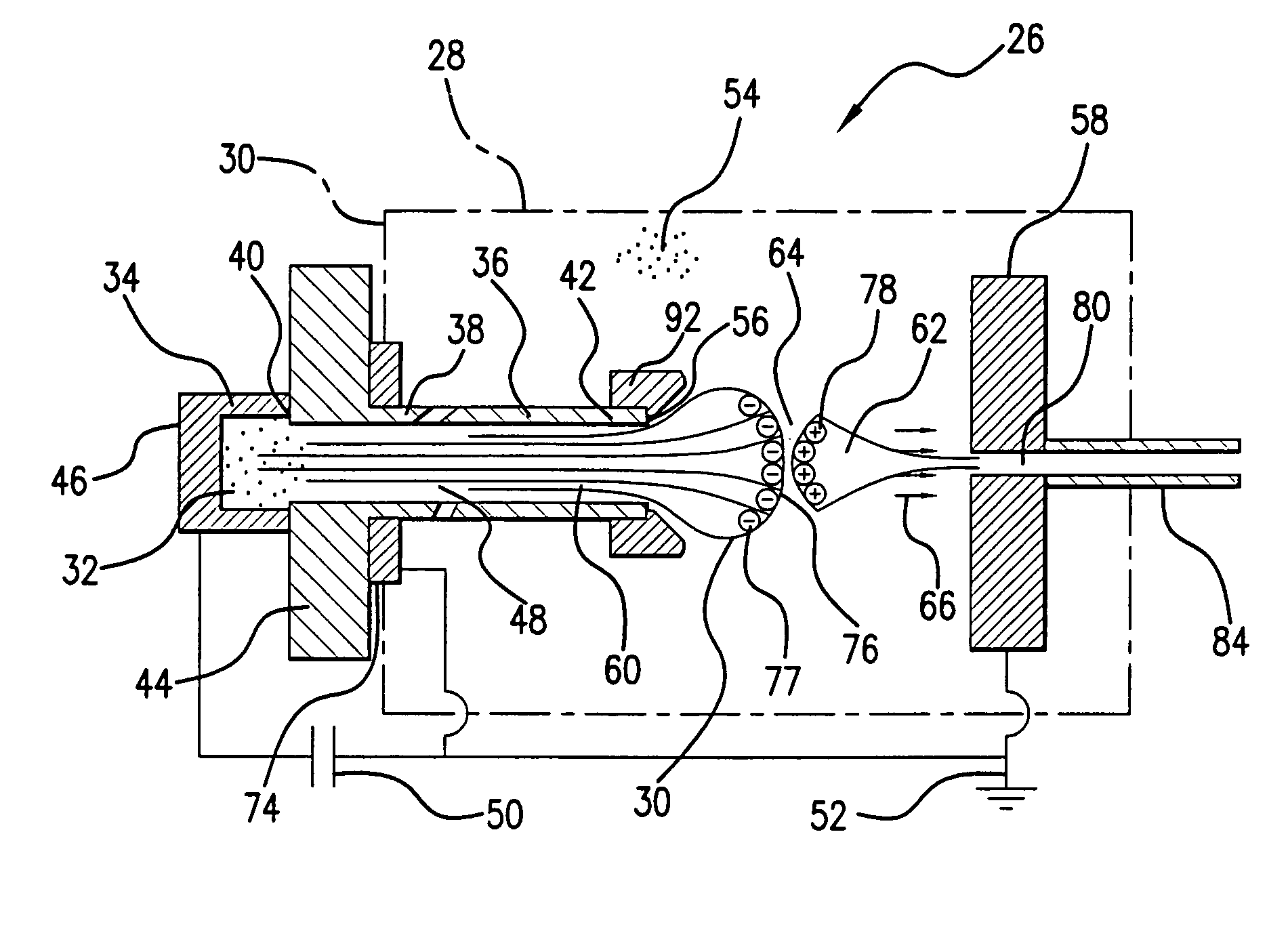
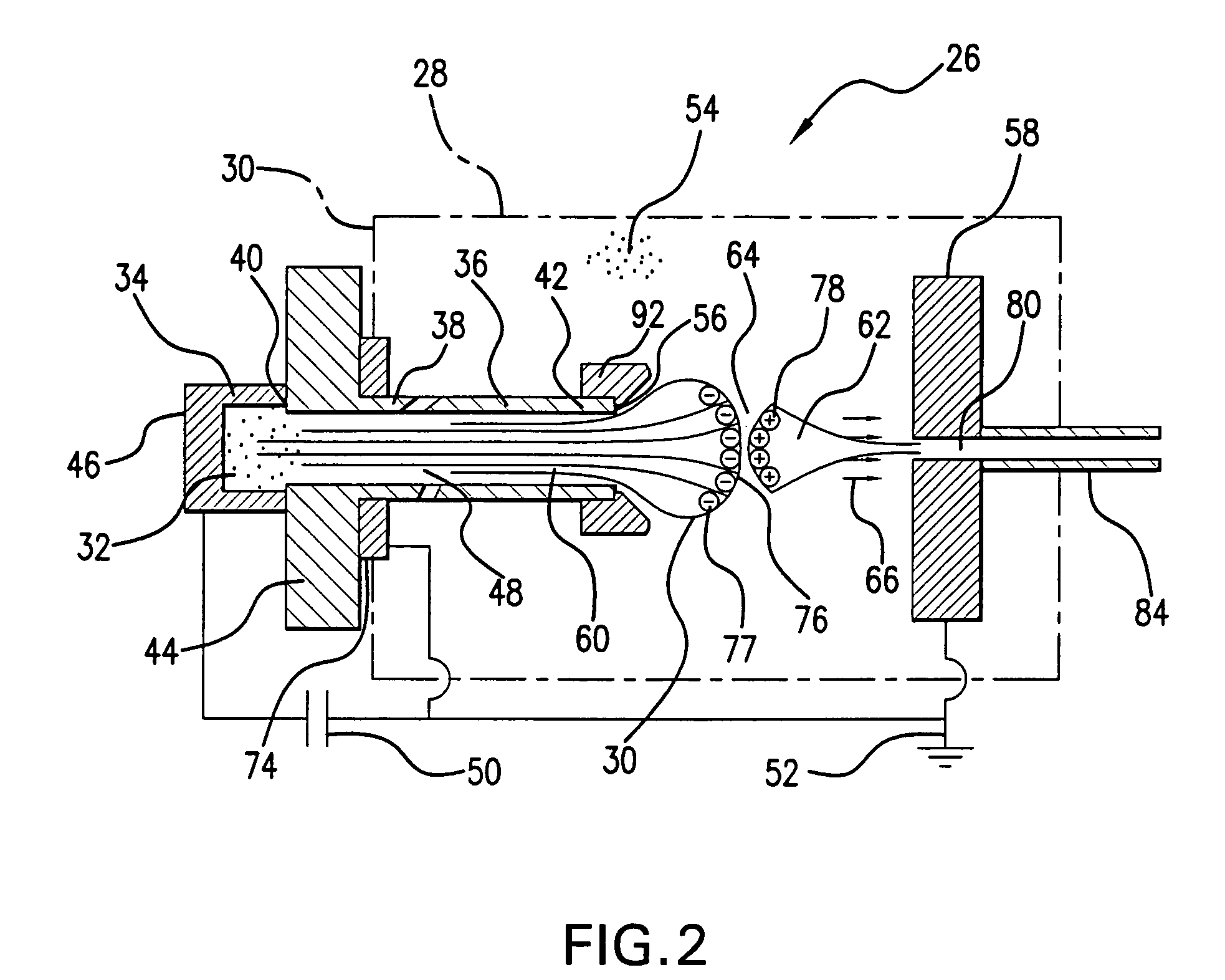
[0047] An ablation plasma generator of the present invention, also referred to herein as a pulsed electron ablation (PEA) apparatus includes a mechanism for generating an electron beam impinging a target surface. This also includes a means for modifying and controlling the expanding plasma to provide elemental compositional uniformity and cleanliness of the resulting stream of species emanating from the target surface for depositing thin films on substrates. The ablation target in the apparatus of the present invention is an integral part of the generator. The ablation target is an active part of the electron beam source rather than just a passive recipient of the electron beam as it significantly affects the dynamics of the beam formation and its parameters.

[0048] Referring to FIGS. 2 and 3, the ablation plasma generator 26 includes a processing chamber 28, at one end 30 of which a pulsed, high-density plasma 32 is created in a reservoir-cathode 34 maintained initially at a negati...


PUM

PropertyMeasurementUnit
distanceaaaaaaaaaa
pressureaaaaaaaaaa
energy levelaaaaaaaaaa

Abstract

A pulsed electron ablation (PEA) utilizes a source of a high power density electron beam which includes a cathode plasma supplying electrons for generation of the electron beam and an anode plasma having a front layer extending in the processing chamber in a counter relationship with the front layer of the cathode plasma. A gas supply line is coupled to the processing chamber to supply a process gas in a controlled fashion to the anode to create a pressure gradient between the anode and the cathode plasma, and to stimulate an intense ionization of the process gas in the vicinity to the anode to form the anode plasma. The power density of the electron beam sharply increases as the result of an interaction of said cathode and anode plasmas at the double space charge contact layer formed between their fronts. A target is positioned in the processing chamber a predetermined distance from the front layer of the cathode plasma and is exposed to the electron beam to produce stream of the ablation plasma.

Description

[0001] The present Utility Patent Application is based on a Provisional Patent Application, Ser. No. 60 / 703,880, filed 1 Aug. 2005.FIELD OF THE INVENTION [0002] This invention relates to the field of plasma generation, and specifically to generation of a pulsed stream of ablation plasma used for deposition of thin films on substrates. [0003] More in particular, the present invention is directed to a pulsed electron ablation (PEA) technique in which a target is exposed to an electron beam, thereby causing ablation of material from the target to form a stream of ablation plasma for thin films deposition. [0004] The present invention is further directed to a PEA apparatus and method which includes a source of electron beams having increased power (power density). The increased power of the electron beams is attained by creating a cathode plasma and a counter anode plasma interacting at a contact layer defined therebetween in a processing chamber, wherein the cathode and anode plasma in...

Claims


Application Information

Patent Timeline
Patent Type & Authority Applications(United States)
IPC IPC(8): C08F2/46
CPCH01J37/3233H01J37/32009
Inventor STRIKOVSKI, MIKHAILKOLAGANI, SOLOMON H.KIM, JEONGGOO
Owner NEOCERA
Why Eureka
Try Eureka