Injection-Locked Oscillator

an injection-locked oscillator and oscillator technology, applied in the direction of oscillation generators, electric devices, pulse automatic control, etc., can solve the problems of injection-locked oscillators, phase comparator and dividers are particularly power-hungry, and are not always suitable for low-power implementations

Inactive Publication Date: 2012-03-29
QUALCOMM TECH INT
View PDF7 Cites 39 Cited by
  • Summary
  • Abstract
  • Description
  • Claims
  • Application Information

AI Technical Summary

Benefits of technology

[0010]According to a first embodiment of the invention, there is provided a signal generator for generating an output signal with a frequency that is a multiple of a frequency of a reference signal, the signal generator comprising an oscillator configured to generate the output signal in dependence on the reference

Problems solved by technology

Although phase-locked loops are effective at generating signals having a wide range of different frequencies from a single frequency reference, they are not always suitable for low-power implementations.
The phase comparator and the divider tend to be particularly power-hungry.
However, injection-locked oscillators have some major d

Method used


Image

  • Injection-Locked Oscillator
  • Injection-Locked Oscillator
  • Injection-Locked Oscillator

Examples


Embodiment Construction

[0034]A signal generator for generating an output signal having a frequency that is a multiple of a frequency of a reference signal may include an oscillator and a control circuit. The oscillator is suitably configured to receive the reference signal. The control circuit is suitably configured to input a series of pulses into the oscillator. The oscillator may then generate an output signal in dependence on both the reference signal and the series of pulses. Preferably the control circuit controls the phase of each pulse so that one or more of the pulses is offset in phase relative to the reference signal. Advantageously, controlling the phase of the pulses may enable the control circuit to control the frequency and / or phase of the signal output by the oscillator.

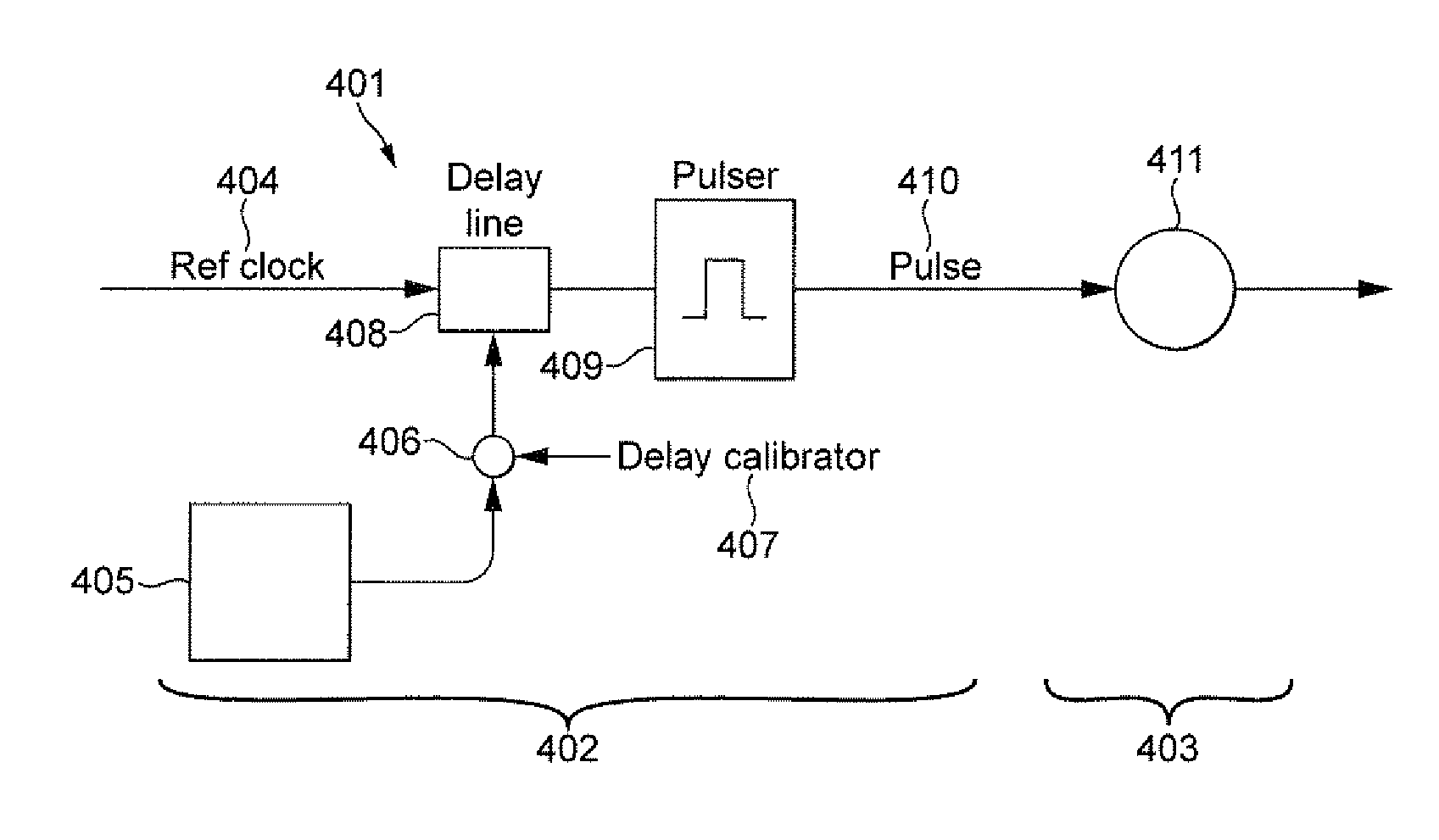
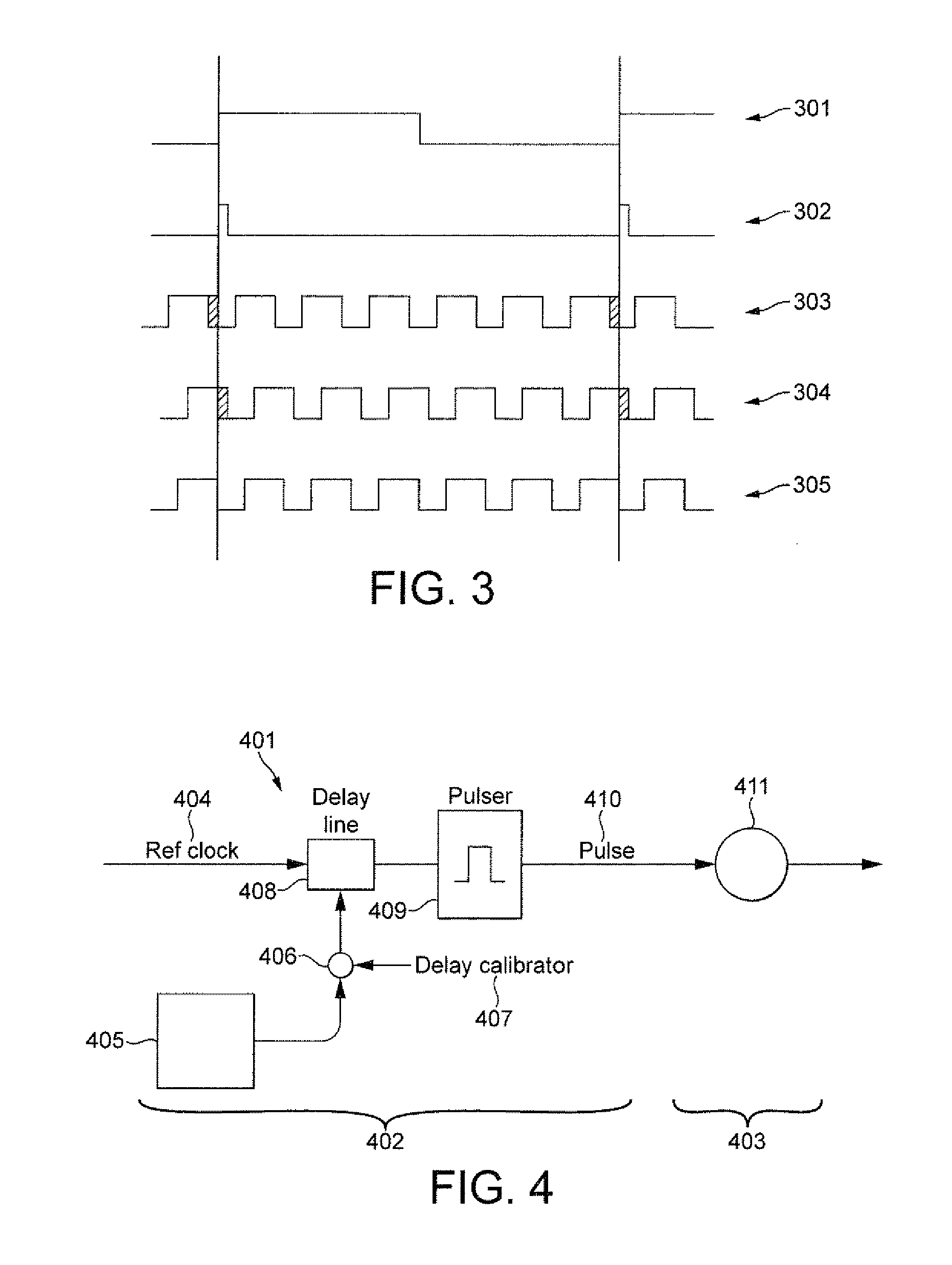
[0035]An example of a signal generator that is arranged to control the frequency and / or phase of an output signal is shown in FIG. 4. The signal generator is shown generally at 401 and comprises a control circuit 402 and an...


PUM


Abstract

A signal generator for generating an output signal with a frequency that is a multiple of a frequency of a reference signal, the signal generator including an oscillator configured to generate the output signal in dependence on the reference signal and a control signal and a control circuit configured to generate the control signal to comprise a series of pulses in which one or more of the pulses is offset in phase relative to the reference signal, the control circuit thereby being capable of controlling the frequency and/or phase of the output signal.

Description

BACKGROUND OF THE INVENTION[0001]The invention relates to an injection-locked oscillator and, in particular, to an injection-locked oscillator that utilises a pulse generator to maintain a phase-alignment between a reference signal and the signal output by the oscillator.[0002]A phase-locked loop is a well known circuit for generating signals having a predetermined frequency relationship with a reference signal. In its most basic form, a phase-locked loop comprises an oscillator that is controlled by means of a feedback loop. The feedback loop takes the output of the oscillator, compares it with a reference signal and adjusts the oscillator accordingly. Typically the feedback loop comprises a divider for dividing the output signal, a phase comparator for comparing the phase of the divided signal with the reference signal and a charge pump for outputting a pulse of charge that either speeds up or slows down the oscillator, in dependence on the phase comparison. The phase-locked loop ...

Claims


Application Information

Patent Timeline
IPC IPC(8): H03B19/00
CPCH03L7/24H03L7/081
Inventor SORNIN, NICOLAS
Owner QUALCOMM TECH INT
Why Eureka
Try Eureka