

Display unit with touch detection function and electronic unit
a display unit and touch detection technology, applied in the field of display units having touch detection functions, can solve the problems of degradation in the s/n ratio of degradation of the accuracy of touch position or the like, etc., and achieve the effect of suppressing the change in the touch detection signal, suppressing the influence of display operation on touch detection, and suppressing the influence of display operation
- Summary
- Abstract
- Description
- Claims
- Application Information
AI Technical Summary
Benefits of technology
Problems solved by technology
Method used
Image

Examples
first embodiment
2. First Embodiment
[Configuration Example]
(General Configuration Example)
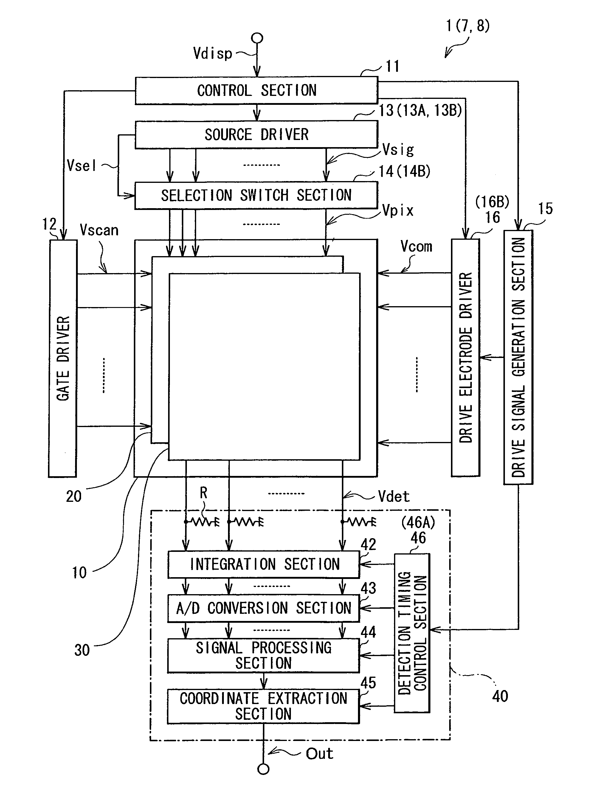
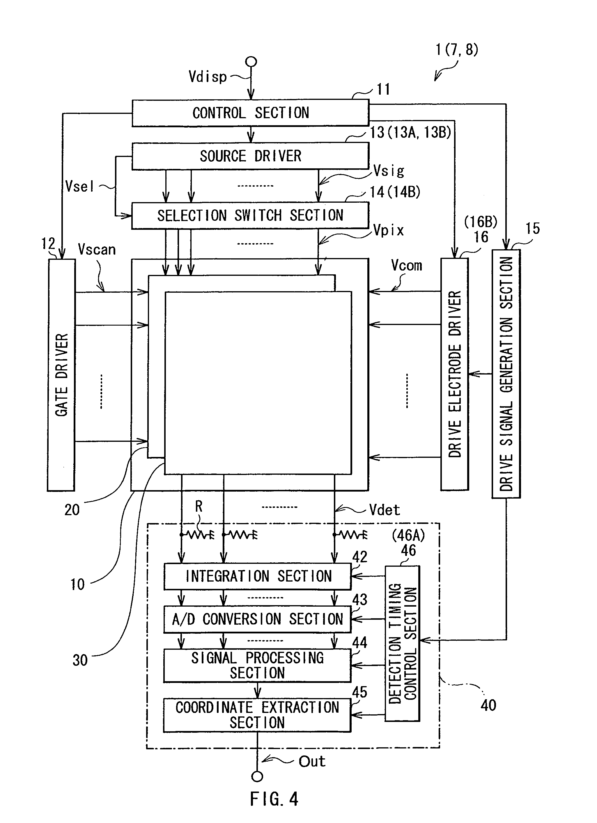
[0054]FIG. 4 illustrates a configuration example of a display unit with a touch detection function according to a first embodiment of the disclosure. The display unit uses a liquid crystal display element as a display element, and is a so-called in-cell type unit, in which a liquid crystal display device configured by the liquid crystal display element is integrated with a capacitance-type touch detection device.
[0055]The display unit with a touch detection function 1 includes a control section 11, a gate driver 12, a source driver 13, a selection switch section 14, a drive signal generation section 15, a drive electrode driver 16, a display device with a touch detection function 10, and a touch detection section 40.
[0056]The control section 11 is a circuit supplying a control signal to each of the gate driver 12, the source driver 13, the drive signal generation section 15, the drive electrode driver 16, and t...
modification 1
[Modification 1]
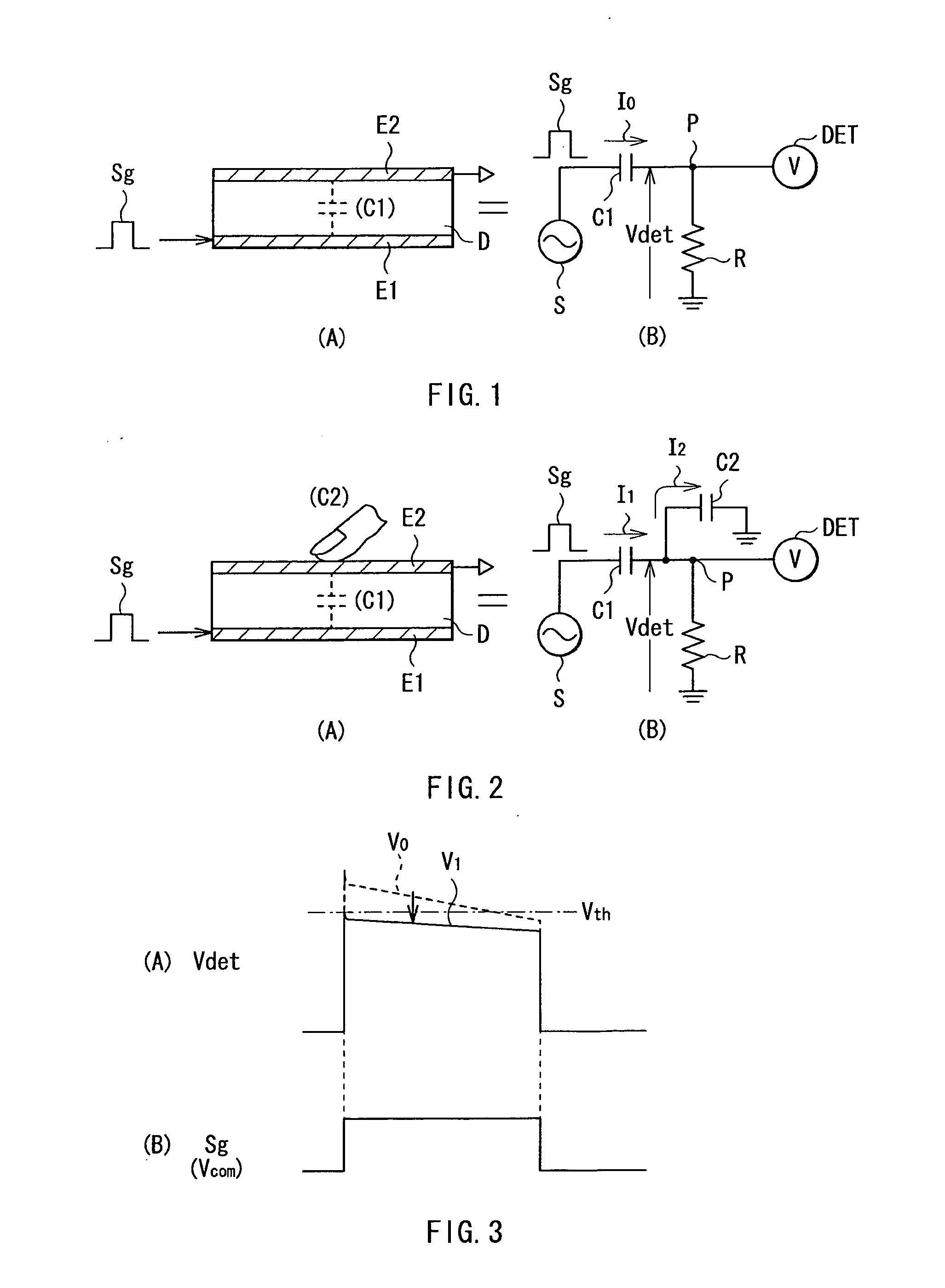
[0121]While the source driver 13 applies the pixel signals Vpix to the pixel signal lines SGL via the selection switch section 14 in the embodiment, this is not limitative. Instead, for example, the source driver 13 may directly apply the pixel signals Vpix to the pixel signal lines SGL after generating the signals. In other words, while each pixel signal line SGL is made to be in a floating state to maintain the voltage of the pixel signal line SGL during the touch detection period in the embodiment, this is not limitative. Instead, for example, a voltage may be directly applied to each pixel signal line SGL to maintain the voltage of the pixel signal line SGL during the touch detection period.
second embodiment
3. Second Embodiment
[0122]Next, a display unit with a touch detection function 7 according to a second embodiment of the disclosure is described. In the embodiment, a predetermined voltage is applied to each pixel signal line SGL during a touch detection period Pt. It is to be noted that substantially the same components as those of the display unit with a touch detection function 1 according to the above-described first embodiment are designated by the same numerals, and description of them is appropriately omitted.
[0123]The display unit with a touch detection function 7 includes a source driver 13A and a detection timing control section 46A as illustrated in FIG. 4.
[0124]The source driver 13A generates a pixel signal Vsig including a predetermined voltage Vp (described later), and generates a switch control signal Vsel necessary for demultiplexing pixel signals Vpix multiplexed into the pixel signal Vsig and separating the predetermined voltage Vp, and supplies the switch control ...
PUM
 Abstract
Description
Claims
Application Information