Light source unit and projector

a technology of light source and projector, which is applied in the direction of non-linear optics, lighting and heating apparatus, instruments, etc., can solve the problems of reducing the utilization efficiency of light source light source, difficulty in incorporating light source, and difficulty in light source encountering, so as to increase the utilization efficiency of excitation light

Active Publication Date: 2012-03-29
CASIO COMPUTER CO LTD +1
View PDF1 Cites 30 Cited by
  • Summary
  • Abstract
  • Description
  • Claims
  • Application Information

AI Technical Summary

Benefits of technology

[0012]According to the aspects of the invention, there can be provided the light source unit including the luminescent plate which includes the luminescent material layer laid on the reflecting surface and which can increase the utilization efficiency of excitation light and luminescent light by forming the irregularities on the excitation light incident surface of the luminescent material layer and the light source which shines excitation light onto the luminescent plate, and the projector which can project the highly luminous image by including the light source described above.

Problems solved by technology

In the light source unit proposed in Japanese Patent No. 3415403, including the three types of laser light sources requires a driving circuit, leading to a problem that the light source encounters difficulty in being incorporated in a projector which tends to be smaller in size and thinner in thickness so as to meet the current market demands.
When the outputs are increased, the respective calorific powers of the light sources are increased, and therefore, a cooling mechanism needs to be enlarged in size, leading to a problem that the light source encounters difficulty in being incorporated in a projector which tends to be smaller in size and thinner in thickness so as to meet the current market demands.
Further, although it is considered that the laser light sources are increased in size in order to realize such an increase in luminance, when the laser light sources are increased in size, the following problems have to be faced.
That is, the enlarged light source encounters difficulty in being incorporated in a projector which tends to be smaller in size and thinner in thickness so as to meet the current market demands, and the utilization efficiency of light of the light source is reduced due to an increased difference between the Etendue of a light source side optical system and the Etendue of a projection side optical system which results from the increased light emitting area.
However, when excitation light is shone normal to a flat plane of the luminescent wheel from a front side thereof, part of light incident on the luminescent material layers passes through the luminescent material layers and is then reflected on a reflecting surface of the luminescent wheel to thereby be emitted from an incident surface of the excitation light towards the excitation light source without exciting the luminescent materials, which happens occasionally, leading to a problem that the utilization efficiency of excitation light is reduced.
Further, since light emitted from the luminescent materials scatters in every direction, part of luminescent light is wasted by being attenuated in the luminescent material layers, leading to a problem that the utilization efficiency of luminescent light is reduced.

Method used


Image

  • Light source unit and projector
  • Light source unit and projector
  • Light source unit and projector

Examples


Embodiment Construction

[0026]Hereinafter, a preferred mode for carrying out the invention will be described by use of the accompanying drawings. Although various limitations which are technically preferable for carrying out the invention are imposed on embodiments which will be described below, the scope of the invention is not limited in any way to the following description and illustrated examples.

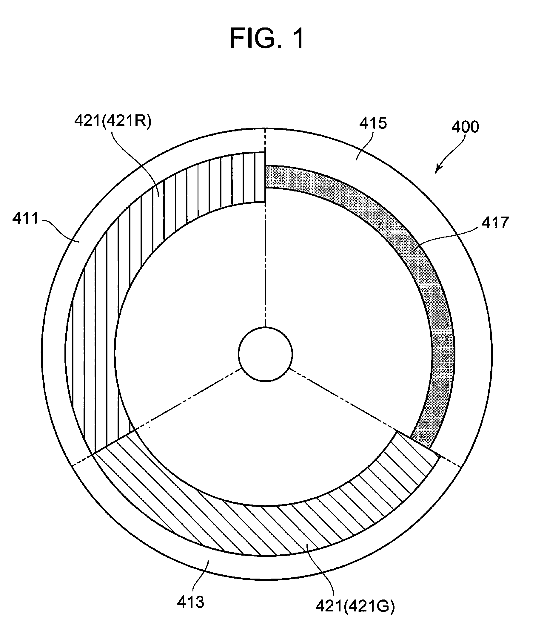
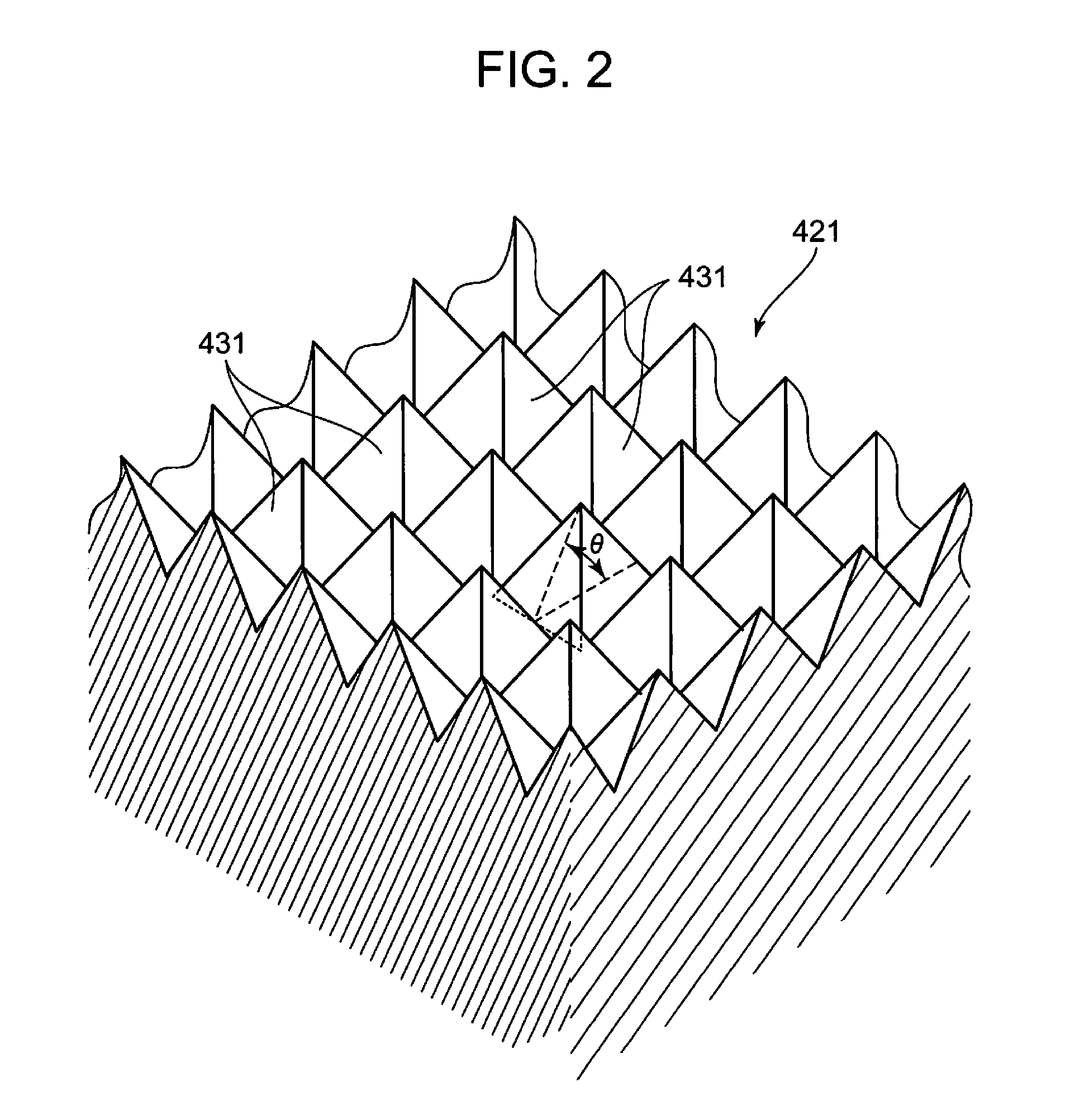
[0027]Hereinafter, an embodiment of the embodiment will be described based on the drawings. FIG. 1 is an exemplary front view of a luminescent plate according to this embodiment, and FIG. 2 is an exemplary drawing showing a surface construction of a luminescent material layer of the luminescent plate. The luminescent plate 400 of this embodiment is, as is shown in the FIG. 1, a circular disk-shaped base on which a red luminescent light emitting area 411, a green luminescent light emitting area 413 and a diffuse transmission area 415 are laid end to end in a circumferential direction; the red luminescent light ...


PUM


Abstract

A light source unit includes an excitation light source and a luminescent wheel on which luminescent light emitting areas including, on a reflecting surface, red and green luminescent materials which respectively emit light of red and green wavelength band, when receiving excitation light, and a diffuse transmission area which diffuses and transmits excitation light, are aligned end to end in a circumferential direction. An excitation light incident surface of a luminescent material layer of the luminescent wheel has a surface with a plurality of projecting bodies. Regular quadrangular pyramids are arranged thereon in a matrix with outer boundaries of bottom portions of adjacent regular quadrangular pyramids contacting each other. The pyramids rise at a rising angle of at least 30°, and a length of one side of an outer boundary of the bottom portion of the pyramid is between 10 and 100 μm.

Description

CROSS-REFERENCE TO RELATED APPLICATIONS[0001]This application is based upon and claims the benefit of priority under 35 USC 119 of Japanese Patent Application No. 2010-213740 filed on Sep. 24, 2010, the entire disclosure of which, including the description, claims, drawings and abstract thereof, is to be incorporated herein by reference.BACKGROUND OF THE INVENTION[0002]1. Field of the Invention[0003]The present invention relates to a light source unit having a luminescent plate and a projector including this light source unit.[0004]2. Description of the Related Art[0005]In these days, data projectors are used on many occasions as image projection apparatuses which project images including images of screens and video images of personal computers, as well as images based on image data which is stored in memory cards on to a screen. These projectors are such that pencils of light which are emitted from a light source are collected to a display device such as a micromirror device called...

Claims


Application Information

Patent Timeline
Patent Type & Authority Applications(United States)
IPC IPC(8): G03B21/14F21V9/16F21V9/40
CPCG03B21/204H04N9/3152H04N9/3114G02B26/00G02F1/13G03B21/14G03B21/20
Inventor OGURA, NAOTSUGUNAKAMURA, HIDEKIMIYAZAKI, TAKESHIUMAMINE, OSAMUMASUDA, HIROKIKAWAKAMI, YASUYUKI
Owner CASIO COMPUTER CO LTD
Why Eureka
Try Eureka