Geothermally cooled power conversion system

a power conversion system and geothermal cooling technology, applied electrical equipment, cooling/ventilation/heating modifications, etc., can solve problems such as excessive heat generation in power conversion systems, and achieve the effects of less energy, less carbon emissions, and improved energy efficiency

Inactive Publication Date: 2012-03-29
ROCKWELL AUTOMATION TECH
View PDF19 Cites 13 Cited by
  • Summary
  • Abstract
  • Description
  • Claims
  • Application Information

AI Technical Summary

Benefits of technology

[0003]Embodiments of the present disclosure provide novel techniques for cooling and / or heating (i.e., thermal conditioning) of power conversion systems. Power conversion systems may house thermally sensitive electronics that are rated for use in certain temperature ranges (e.g., 0° C. to 50° C.). Accordingly, thermal energy may be transferred to and from such electronics devices by the use of fluids (e.g., air, water, glycol, alcohol, etc.) powered by electrical devices such as fans and / or pumps. The fluid flow may transfer the thermal energy through heat exchangers so as to maintain the power conversion systems at a suitable temperature range. The cooling and heating embodiments described herein incorporate geothermal heat exchangers that may use less energy, produce less carbon emissions, and may provide thermal conditioning of power conversion equipment in a variety of climate zones, including tropical zones, deserts, and cold climate zones. In particular, certain embodiments of the thermal conditioning techniques described herein may combine geothermal heat exchangers with the use of traditional electrical fans and / or pumps. Indeed, in certain embodiments, the geothermal techniques described herein are capable of combining with other thermal conditioning techniques (e.g., electrical fans and pumps) in order to achieve improved energy efficiencies. In other embodiments, the geothermal techniques described herein are capable of replacing the use of, for example, electrical fans and pumps, resulting in even higher energy efficiencies.

Problems solved by technology

Unfortunately, power conversion systems may generate excessive heat.

Method used


Image

  • Geothermally cooled power conversion system
  • Geothermally cooled power conversion system
  • Geothermally cooled power conversion system

Examples


Embodiment Construction

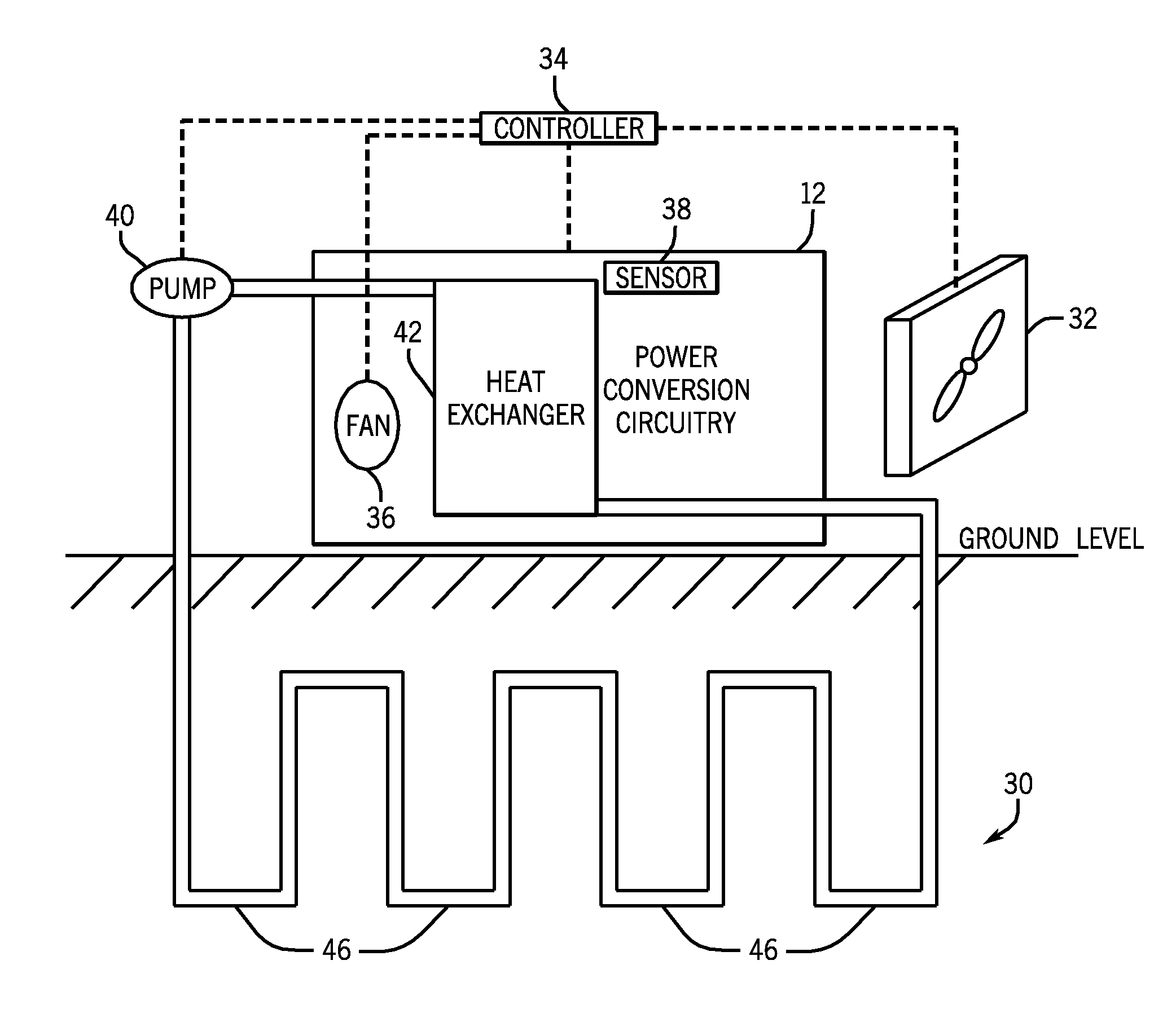
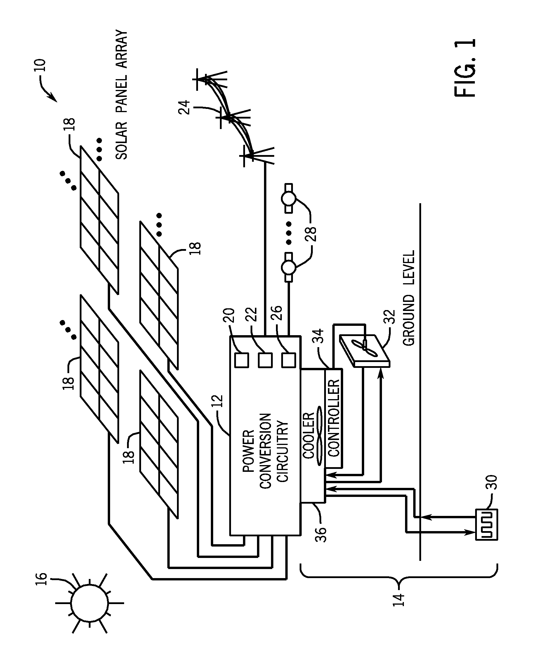
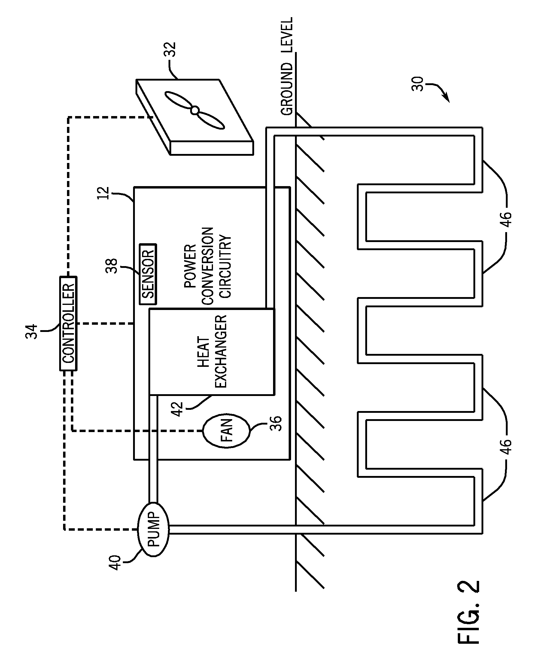
[0012]It may be beneficial to first discuss embodiments of certain power generation systems that may incorporate the techniques described herein. With this in mind, FIG. 1 is a schematic diagram of an embodiment of a solar power generation system 10 including power conversion circuitry 12 and a geothermal conditioning system 14. A power source, such as the sun 16, generates an electromagnetic radiation (e.g., sunlight), some of which may impinge upon a plurality of solar panels 18. The solar panels 18 may use, for example, a photovoltaic effect to convert the impinging solar radiation into a direct current (DC) flow of electrons. It is to be understood that while the depicted embodiment shows four solar panels 18, more or fewer solar panels 18 may be used.

[0013]The solar panels 18 may direct the resulting DC power into power conversion circuitry 12. In certain embodiments, the power conversion circuitry 12 may include, for example, power inverters 20, rectifiers 22, and other electr...


PUM


Abstract

Embodiments of the present invention provide novel techniques for cooling power conversion circuitry. In particular, a geothermal conditioning system may be used that includes a ground loop heat exchanger. The ground loop heat exchanger may pump heat from the power conversion circuitry into the ground in order to cool the power conversion circuitry. The ground loop heat exchanger may also extract heat from the ground and direct the heat into the power conversion circuitry in order to heat the power conversion circuitry. The geothermal conditioning system may also include a surface loop heat exchanger and combine the cooling and heating abilities of both the ground loop and surface loop heat exchangers in order to improve energy efficiency.

Description

BACKGROUND[0001]The present invention relates generally to the field of power conversion systems. More particularly, the present invention relates to power conversion systems that are thermally conditioned by geothermal heat exchangers.[0002]Power conversion systems, such as solar drives, are typically used to convert an incoming direct current (DC) into an alternating current (AC). In solar applications, the emissions of solar radiation may be captured, for example, by using photovoltaic cells, and converted into DC power. The power conversion system may then convert the DC power into AC power suitable for distribution, for example, into an electric grid. Unfortunately, power conversion systems may generate excessive heat.BRIEF DESCRIPTION[0003]Embodiments of the present disclosure provide novel techniques for cooling and / or heating (i.e., thermal conditioning) of power conversion systems. Power conversion systems may house thermally sensitive electronics that are rated for use in ...

Claims


Application Information

Patent Timeline
Patent Type & Authority Applications(United States)
IPC IPC(8): H05K7/20H02M1/00
CPCH05K7/20936H02M7/003
Inventor AHANGAR, ABDOLMEHDI KAVEHDAY, SCOTT D.
Owner ROCKWELL AUTOMATION TECH
Why Eureka
Try Eureka