Microphone Array System

a microphone array and microphone technology, applied in the direction of instruments, loudspeakers, direction finders using ultrasonic/sonic/infrasonic waves, etc., can solve the problems of unsuitability of conventional narrowband techniques employed in conventional microphone arrays, inability to effectively implement parametric single microphones, and generally unsuitable hands-free or handheld speech acquisition devices. achieve the effect of partially suppressing ambient noise signals, and enhancing the target sound signal received

Active Publication Date: 2012-03-29
VOCALIFE LLC +1
View PDF4 Cites 169 Cited by
  • Summary
  • Abstract
  • Description
  • Claims
  • Application Information

AI Technical Summary

Benefits of technology

[0008]The sound source localization unit estimates a spatial location of the target sound signal from the received sound signals, for example, using a steered response power-phase transform. The adaptive beamforming unit performs adaptive beamforming for steering a directivity pattern of the microphone array in a direction of the spatial location of the target sound signal. The adaptive beamforming unit thereby enhances the target sound signal from the target sound source and partially suppresses the ambient noise signals. The noise reduction unit suppresses the ambient noise signals for further enhancing the target sound signal received from the target sound source.

Problems solved by technology

However, the paradigm of a single microphone often does not work effectively because the microphone picks up many ambient noise signals in addition to the desired sound, specifically when the distance between a user and the microphone is more than a few inches.
Conventional microphone arrays include arrays that are typically developed for applications such as radar and sonar, but are generally not suitable for hands-free or handheld speech acquisition devices.
The main reason is that the desired sound signal has an extremely wide bandwidth relative to its center frequency, thereby rendering conventional narrowband techniques employed in the conventional microphone arrays unsuitable.
In order to cater to such broadband speech applications, the array size needs to be vastly increased, making the conventional microphone arrays large and bulky, and precluding the conventional microphone arrays from having broader applications, for example, in mobile and handheld communication devices.

Method used


Image

  • Microphone Array System
  • Microphone Array System
  • Microphone Array System

Examples


Embodiment Construction

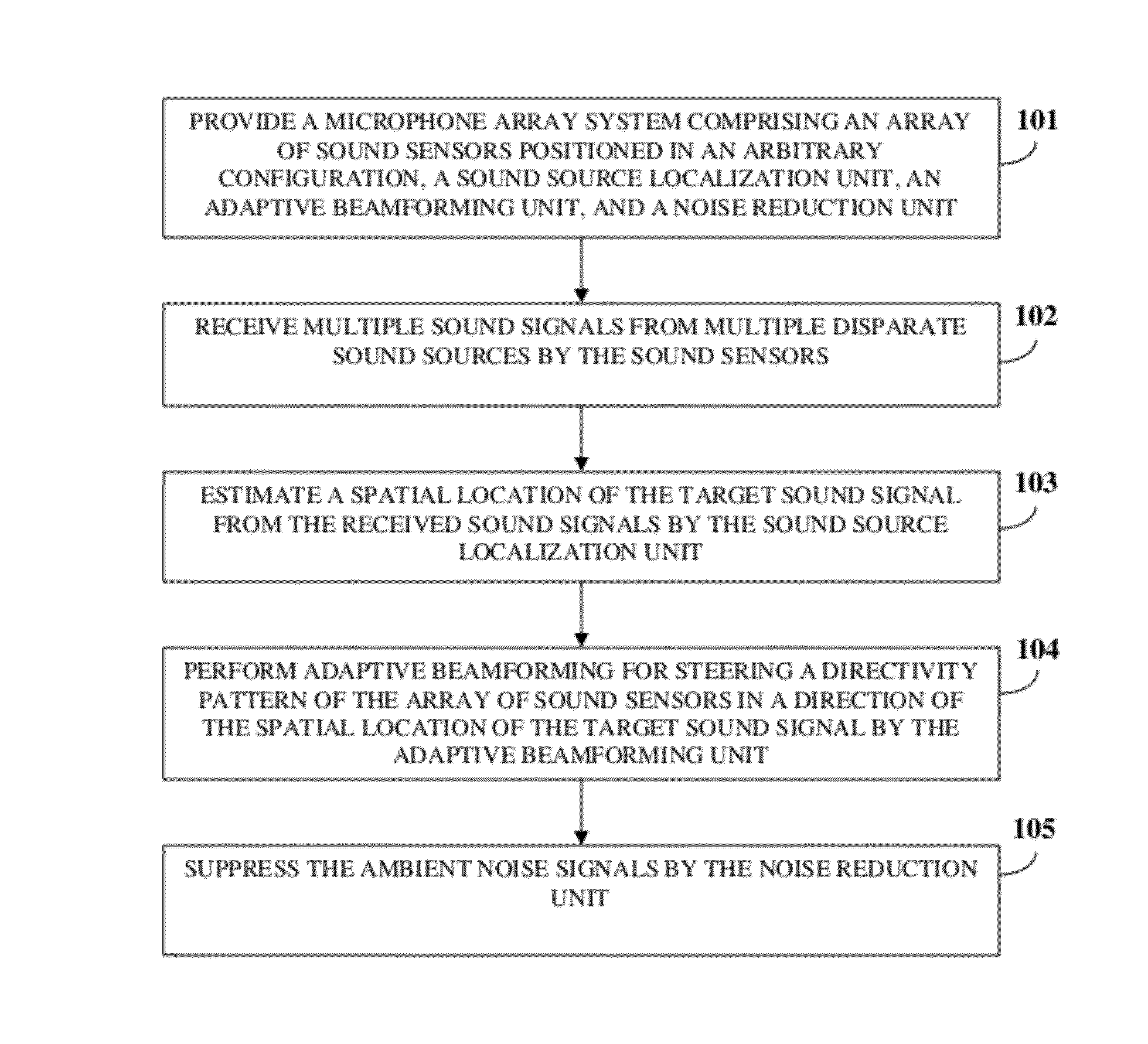
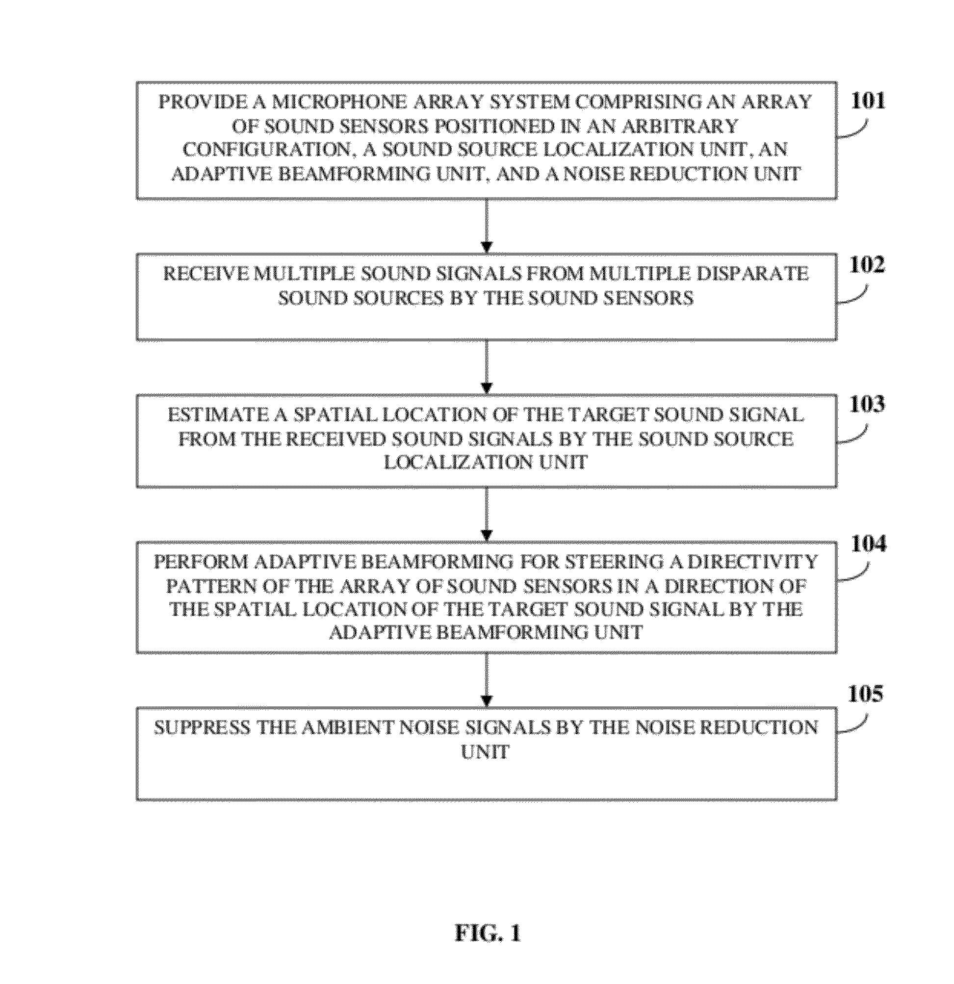
[0044]FIG. 1 illustrates a method for enhancing a target sound signal from multiple sound signals. As used herein, the term “target sound signal” refers to a desired sound signal from a desired or target sound source, for example, a person's speech that needs to be enhanced. The method disclosed herein provides 101a microphone array system comprising an array of sound sensors positioned in an arbitrary configuration, a sound source localization unit, an adaptive beamforming unit, and a noise reduction unit. The sound source localization unit, the adaptive beamforming unit, and the noise reduction unit are in operative communication with the array of sound sensors. The microphone array system disclosed herein employs the array of sound sensors positioned in an arbitrary configuration, the sound source localization unit, the adaptive beamforming unit, and the noise reduction unit for enhancing a target sound signal by acoustic beam forming in the direction of the target sound signal i...


PUM


Abstract

A method and system for enhancing a target sound signal from multiple sound signals is provided. An array of an arbitrary number of sound sensors positioned in an arbitrary configuration receives the sound signals from multiple disparate sources. The sound signals comprise the target sound signal from a target sound source, and ambient noise signals. A sound source localization unit, an adaptive beamforming unit, and a noise reduction unit are in operative communication with the array of sound sensors. The sound source localization unit estimates a spatial location of the target sound signal from the received sound signals. The adaptive beamforming unit performs adaptive beamforming by steering a directivity pattern of the array of sound sensors in a direction of the spatial location of the target sound signal, thereby enhancing the target sound signal and partially suppressing the ambient noise signals, which are further suppressed by the noise reduction unit.

Description

CROSS REFERENCE TO RELATED APPLICATIONS[0001]This application claims the benefit of provisional patent application No. 61 / 403,952 titled “Microphone array design and implementation for telecommunications and handheld devices”, filed on Sep. 24, 2010 in the United States Patent and Trademark Office.[0002]The specification of the above referenced patent application is incorporated herein by reference in its entirety.BACKGROUND[0003]Microphones constitute an important element in today's speech acquisition devices. Currently, most of the hands-free speech acquisition devices, for example, mobile devices, lapels, headsets, etc., convert sound into electrical signals by using a microphone embedded within the speech acquisition device. However, the paradigm of a single microphone often does not work effectively because the microphone picks up many ambient noise signals in addition to the desired sound, specifically when the distance between a user and the microphone is more than a few inch...

Claims


Application Information

Patent Timeline
Patent Type & Authority Applications(United States)
IPC IPC(8): G10K11/16
CPCH04R3/005G01S3/801G01S5/22H04R1/406H04R2201/401H04R2201/403H04M3/568G01S3/8055
Inventor ZHU, MANLILI, QI
Owner VOCALIFE LLC
Why Eureka
Try Eureka