

Phantom Power Circuit
- Summary
- Abstract
- Description
- Claims
- Application Information
AI Technical Summary
Benefits of technology
Problems solved by technology
Method used
Image

Examples
Embodiment Construction
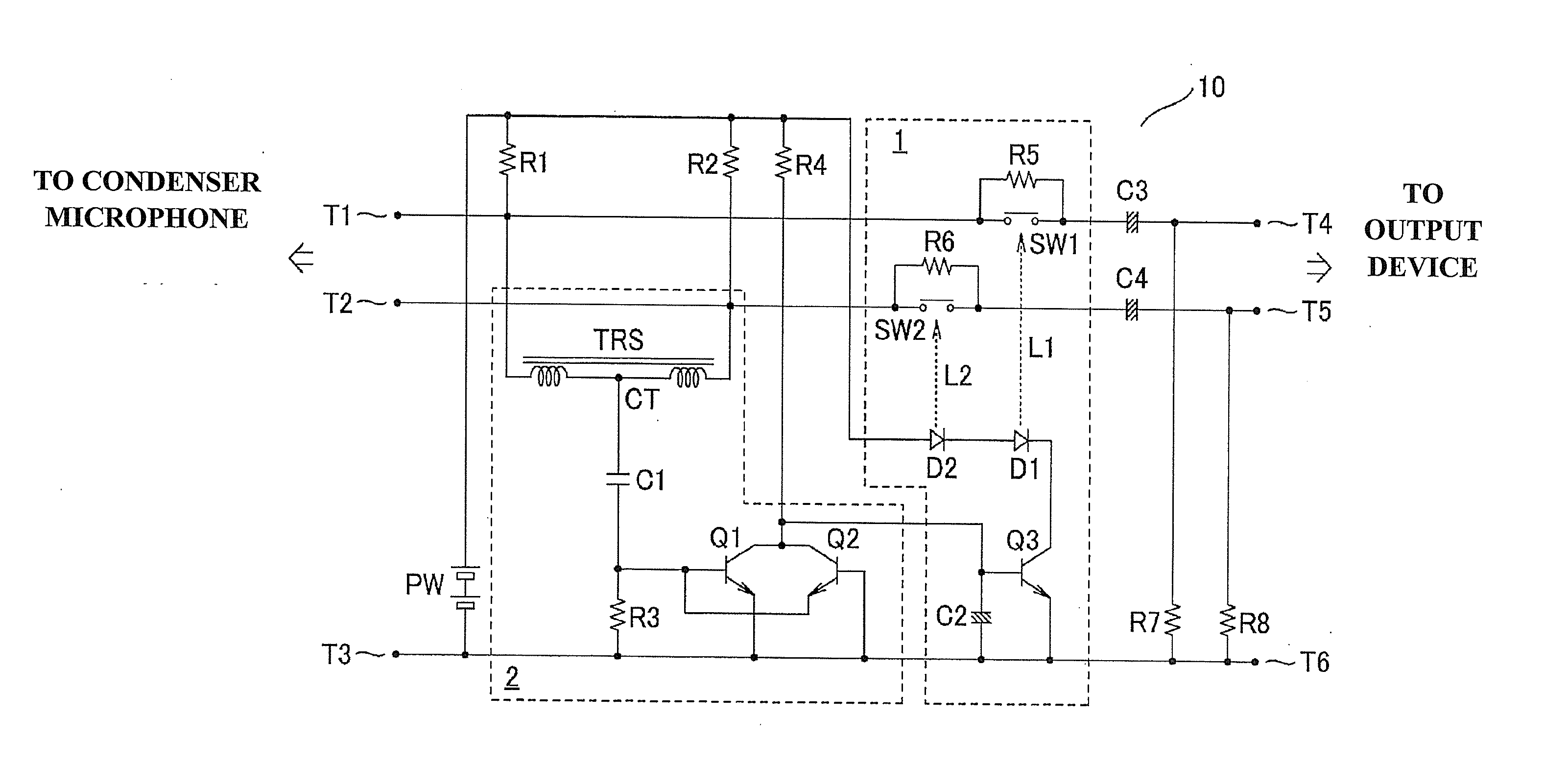
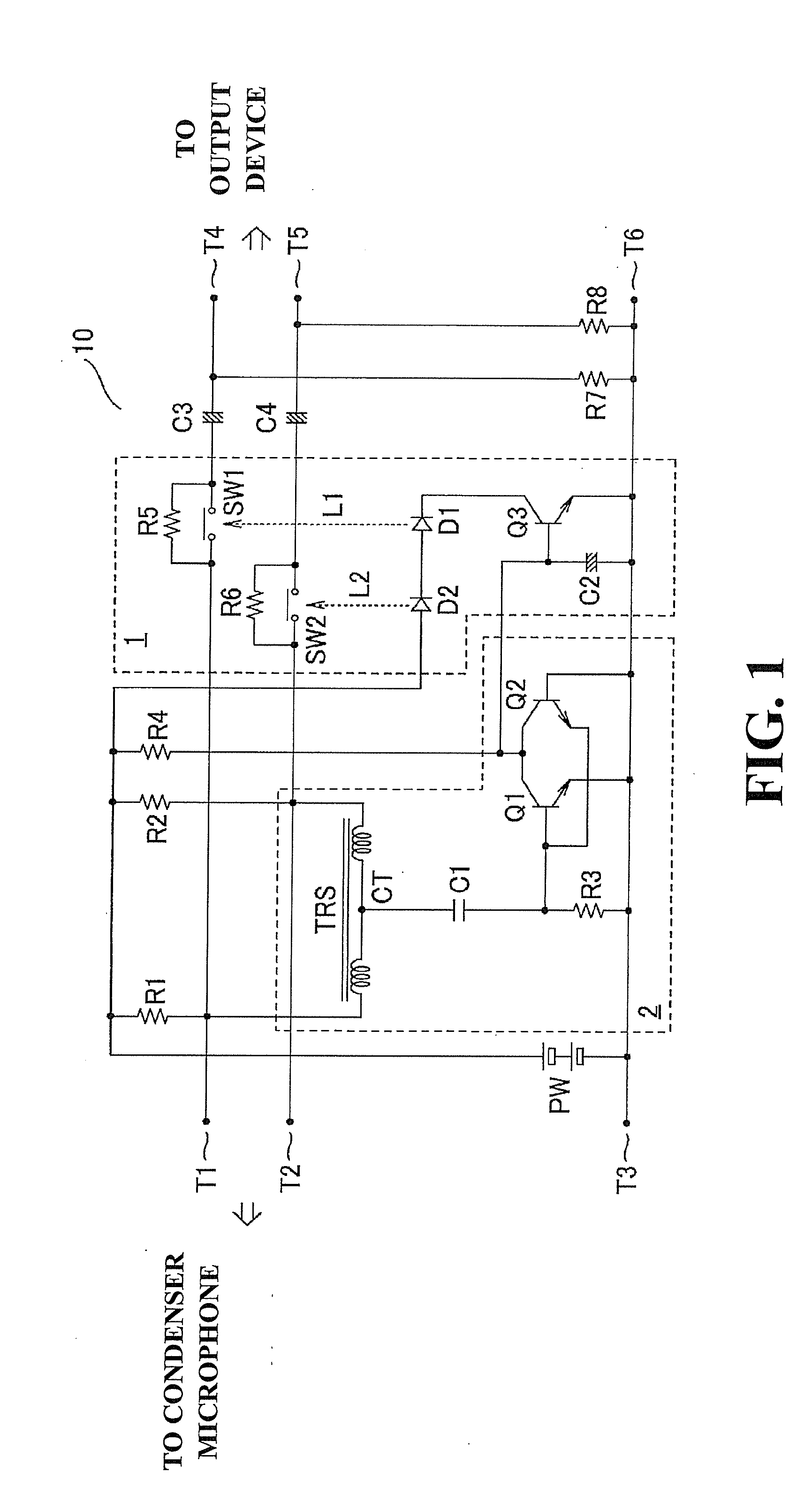
[0015]A phantom power circuit according to an embodiment of the present invention is explained with reference to FIG. 1. FIG. 1 is a circuit diagram of the phantom power circuit according to the embodiment of the present invention. A phantom power circuit 10 includes a power source PW that supplies DC power and supply resistors R1 and R2 between terminals (T1, T2, and T3) connected to a condenser microphone (not shown in the drawing) and terminals (T4, T5, and T6) connected to an output device (e.g., an amplifier). Furthermore, a limiting circuit 1 and a detection circuit 2 are provided, which are characteristic of the phantom power circuit of the present invention.
[0016]The terminal T1 is connected to a HOT terminal of the condenser microphone (not shown in the drawing). The terminal T2 is connected to a COLD terminal of the condenser microphone. The terminal T3 is connected to a ground terminal. The power is supplied from the power source PW to the condenser microphone through the...
PUM
 Abstract
Description
Claims
Application Information