Preload releasing fastener and release system using same

Inactive Publication Date: 2012-03-29
SPACE SYST LORAL INC
View PDF5 Cites 11 Cited by
  • Summary
  • Abstract
  • Description
  • Claims
  • Application Information

AI Technical Summary

Benefits of technology

[0008]A preload reducing fastener adapted to be fastened into a system in which includes a release system. The fastener may have an integral collar which is adapted to change shape, as in the case of

Problems solved by technology

Although useful in many applications, these devices imparted high shock loads

Method used


Image

  • Preload releasing fastener and release system using same
  • Preload releasing fastener and release system using same
  • Preload releasing fastener and release system using same

Examples


Embodiment Construction

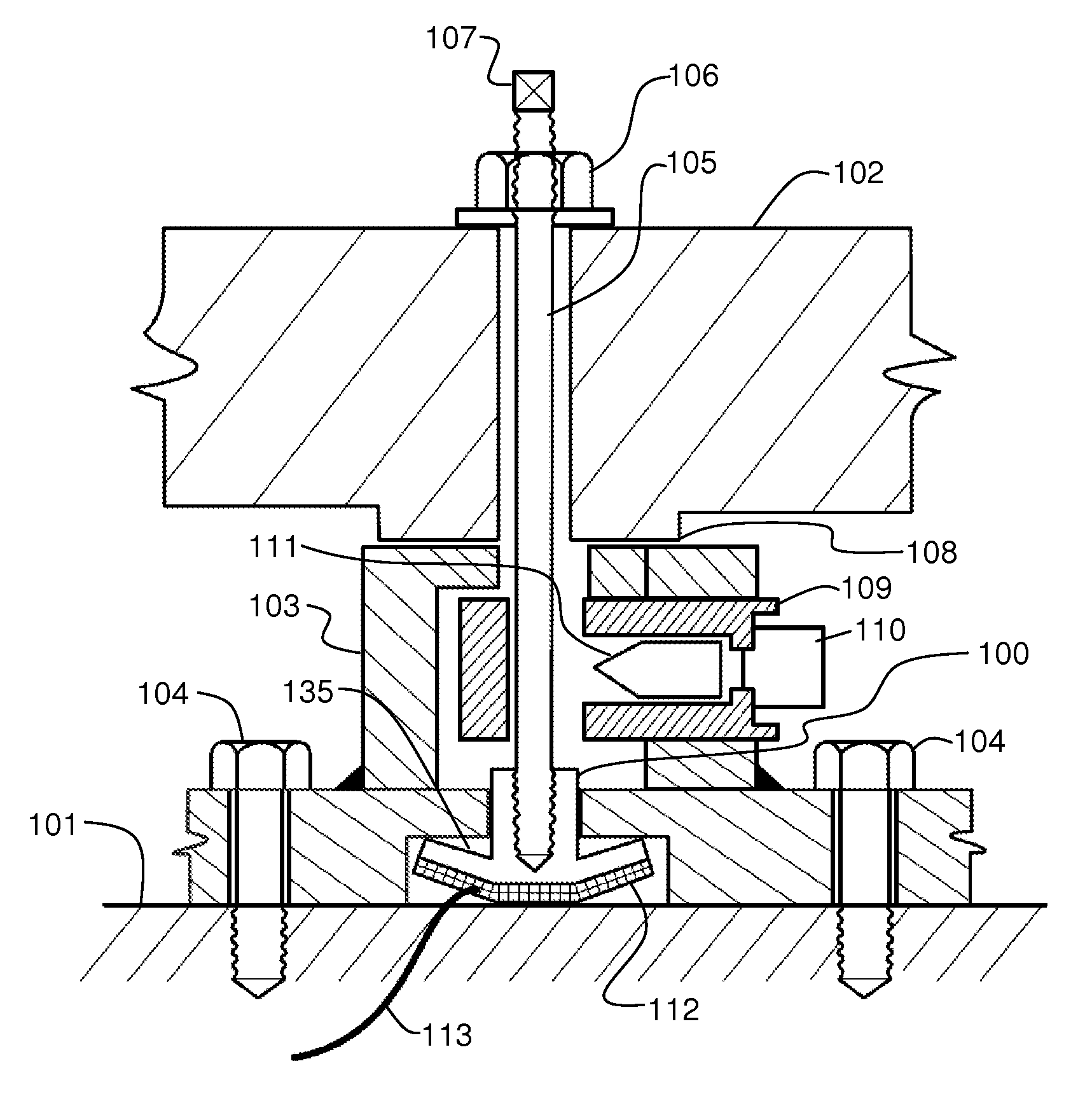
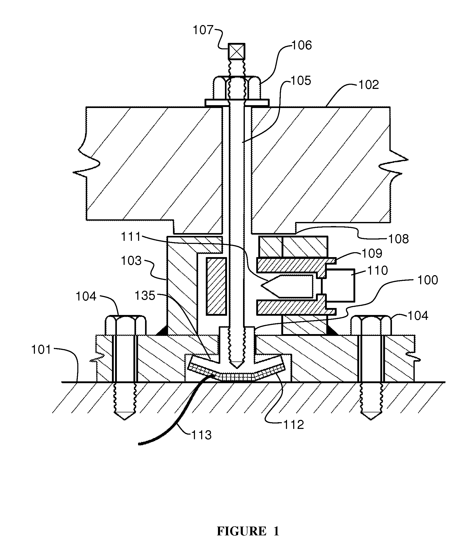
[0014]In some embodiments of the present invention, as seen in FIG. 1, an item to be deployed 102 is seen held down to a surface 101. In some aspects, the item to be deployed 102 may be a solar array panel, an antenna, or other item. In some aspects, the surface 101 may be a spacecraft sidewall. When used during spacecraft launch, a tensioned release device may allow for sufficient holding force of a deployable object, and be used in enough positions, such that the item to be deployed is able to withstand launch loads without damage. A variety of hold-down locations may be used to not only provide strength but to alter, or lower, the frequency of the non-deployed (stowed) system during launch.

[0015]In some aspects, the item 102 may need to be deployed after launch in order to perform its mission tasks. For example, a solar array panel, which may have been part of a stowed array of panels, may need to be deployed in order to become part of a deployed array of panels in order to provi...


PUM


Abstract

A preload reducing fastener adapted to be fastened into a system in which includes a release system. The fastener may have an integral collar which is adapted to change shape, as in the case of a shape memory alloy. The application of heat to fastener may deform the collar such that the fastener may move axially in the load direction, thus reducing the preload previously held by the fastener. A preload reducing device including a preload reducing fastener may include an outer case adapted to center and capture a preload reducing fastener. The case may center the fastener in a desired location in a preloaded system, and may also capture the fastener after release of the system.

Description

CROSS-REFERENCE TO RELATED APPLICATIONS[0001]This application claims priority to U.S. Provisional Patent Application No. 61 / 386,568 to Baghdasarian, filed Sep. 27, 2010.BACKGROUND[0002]1. Field of the Invention[0003]The present invention relates to a preload releasing fastener which may be used in systems which release such items as antennas, solar arrays, positioning mechanisms, and other devices.[0004]2. Description of Related Art[0005]A release apparatus may be used to release a captured member which constrains the deployment of a spacecraft element, such as a solar array and / or reflectors, in the stowed position. In many prior art devices, the spacecraft element was restrained with a wire or a holddown rod system which was released using a pyrotechnic device. Typically, the pyrotechnic device would fire an anvil against a base, with the wire or rod to be cut and released. Although useful in many applications, these devices imparted high shock loads into the units which they were...

Claims


Application Information

Patent Timeline
IPC IPC(8): F16B37/00F16B33/00F16B1/00
CPCB64G1/222Y10T403/21F16B31/005
Inventor BAGHDASARIAN, VAROUJ G.
Owner SPACE SYST LORAL INC
Why Eureka
Try Eureka