
Multi-lumen ventricular drainage catheter

Inactive Publication Date: 2012-03-29
DEPUY SYNTHES PROD INC
View PDF18 Cites 9 Cited by
  • Summary
  • Abstract
  • Description
  • Claims
  • Application Information

AI Technical Summary

Benefits of technology

[0010]The present invention provides a shunt that includes a housing having an inlet, an outlet and a flow control mechanism disposed within the housing. A ventricular catheter is connected to the inlet of the housing. The catheter has a longitudinal length, a proximal end, a distal end,

Problems solved by technology

Blockage of the flow of CSF consequently creates an imbalance between the amount of CSF produced by the choroid plexus and the rate at which CSF is absorbed into the bloodstream, thereby increasing pressure on the brain, which causes the ventricles to enlarge.
The most common complication with shunting is obstruction of the system.
Although obstruction or clogging may occur at any point along the shunt system, it most frequently occurs at the ventricular end of the shunt system.
This process can be ineffective, however, due to the small size of the apertures of the ventricular catheter and due to the small amount of flushing liquid available in the shunt system.
As with the process of backflushing, using a built-in mechanism to flush the shunt system can also fail to remove the obstruction due to factors such as the size of the apertures and the degree and extent to which the apertures have been clogged.
These repairs, however, may be incapable of removing obstructions from the ventricular catheter depending on the location of the clogged apertures.
Another disadvantage of creating new apertures to repair an occluded ventricular catheter is that this method fails to prevent or reduce the risk of repeated obstructions.
Because attempts at flushing or repairing a blocked ventricular catheter are often futile and ineffective, occlusion is more often treated by replacing the catheter.
Although this can be accomplished by removing the obstructed catheter from the ventricle, the growth of the choroid plexus and other tissues around the catheter and into the apertures can hinder removal and replacement of the catheter.
Not only do these procedures pose a significant risk of injury to the patient, they can also be very costly, especially when shunt obstruction is a recurring problem.

Method used


Image

  • Multi-lumen ventricular drainage catheter
  • Multi-lumen ventricular drainage catheter
  • Multi-lumen ventricular drainage catheter

Examples


Embodiment Construction

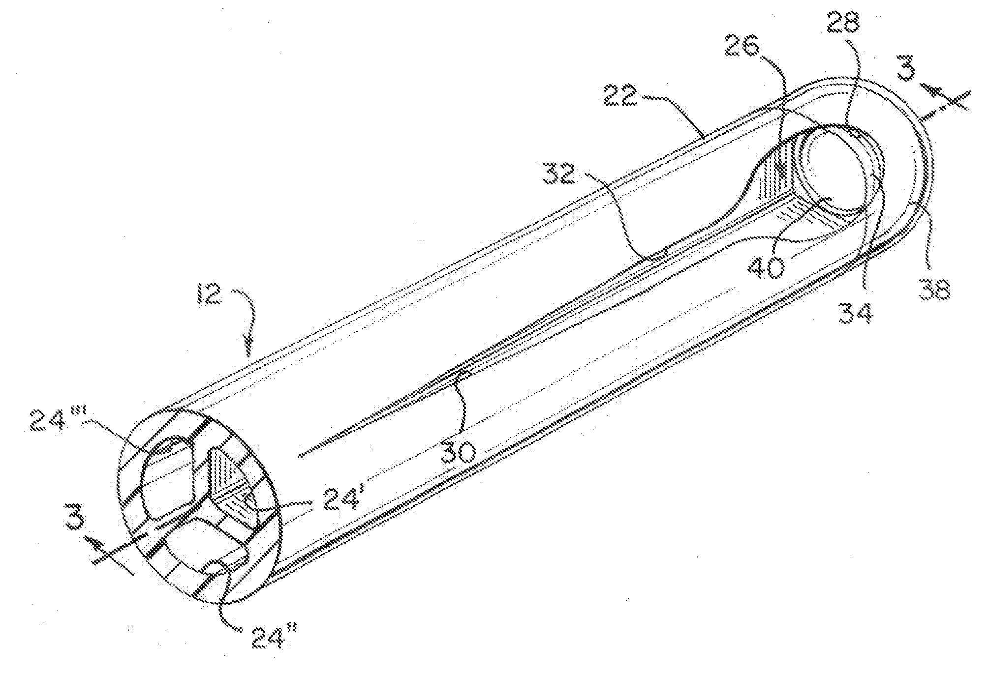
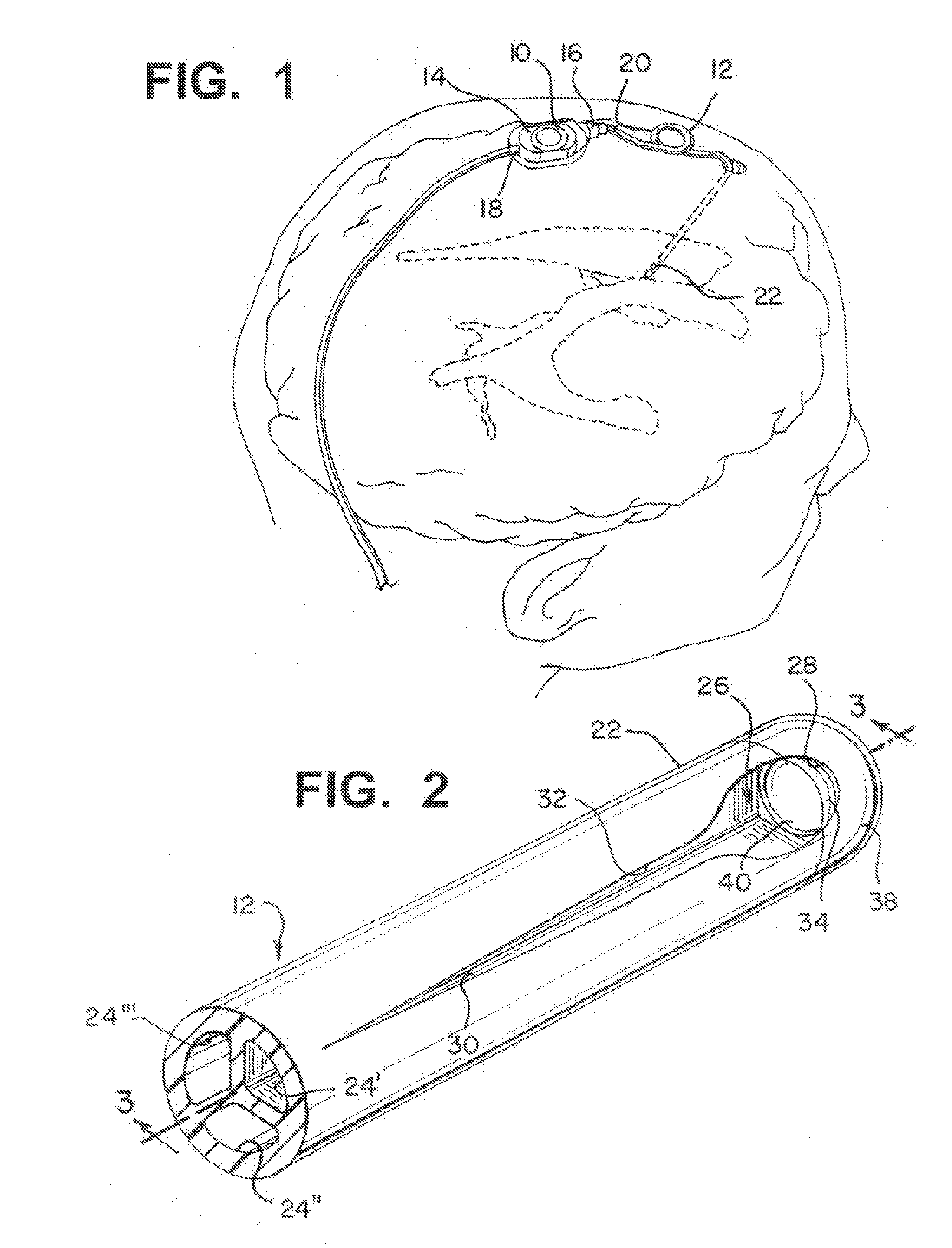
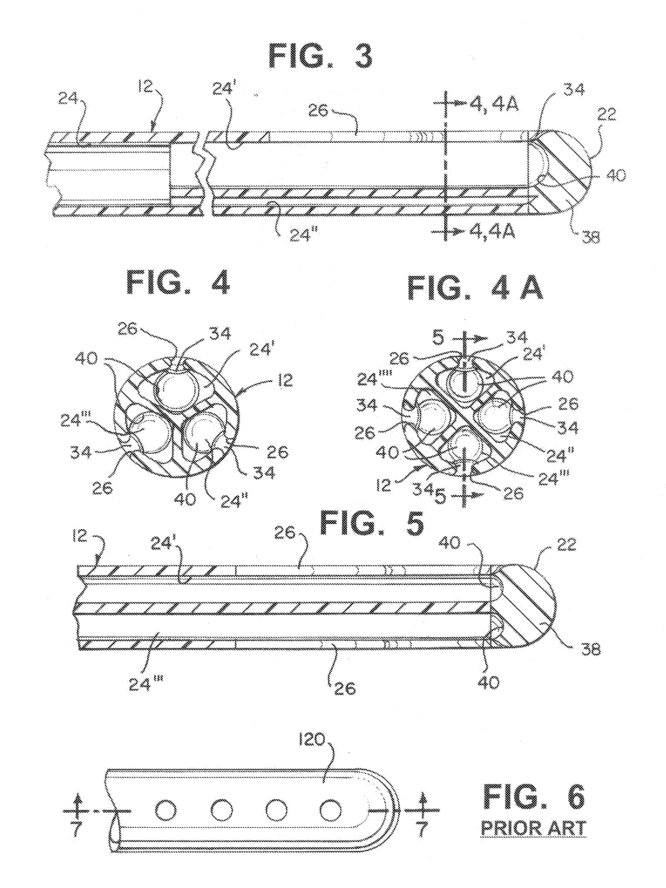
[0021]Referring now to FIGS. 1-5, 8A, 8B and 9 a shunt 10 and a ventricular catheter 12 in accordance with the present invention is illustrated.

[0022]As illustrated in FIG. 1, shunt 10 has a housing 14, which has an inlet 16, an outlet 18 and a flow control mechanism disposed therein. Ventricular catheter 12 is connected to inlet 16 of the housing. Catheter 12 has a longitudinal length, a proximal end 20, a distal end 22, and an inner lumen 24 extending therethrough. Inner lumen 24 is a single lumen at proximal end 20 of the catheter and is comprised of two or more lumens 241, 2411, 24111, 241111, etc. at the distal end 22 of catheter 12. Catheter 12 is preferably made of silicone. In addition, catheter 12 can be impregnated with antimicrobial antibiotics, such as the CODMAN® BACTISEAL® catheter, which is commercially sold by Codman & Shurtleff, Inc. of Raynham, Mass.

[0023]Ventricular catheter 12 has only one aperture 26 at distal end 22 of catheter 12 corresponding to each of the l...


PUM


Abstract

A shunt includes a housing having an inlet, an outlet and a flow control mechanism disposed within the housing. A ventricular catheter is connected to the inlet of the housing. The catheter has a longitudinal length, a proximal end, a distal end, and an inner lumen extending therethrough. The inner lumen of the catheter includes at least two lumens at the distal end and has only one lumen at the proximal end. The catheter has one slit and aperture corresponding to each of the at least two lumens located at the distal end of the catheter.

Description

FIELD OF THE INVENTION[0001]The present invention relates generally to a shunt and a catheter having a system for reducing the risk of blockage or obstruction of the catheter apertures and also increases the ease of revision surgery if the catheter is removed.BACKGROUND OF THE INVENTION[0002]Hydrocephalus is a neurological condition that is caused by the abnormal accumulation of cerebrospinal fluid (CSF) within the ventricles, or cavities, of the brain. CSF is a clear, colorless fluid that is primarily produced by the choroid plexus and surrounds the brain and spinal cord. CSF constantly circulates through the ventricular system of the brain and is ultimately absorbed into the bloodstream. CSF aids in the protection of the brain and spinal cord. Because CSF keeps the brain and spinal cord buoyant, it acts as a protective cushion or “shock absorber” to prevent injuries to the central nervous system.[0003]Hydrocephalus, which affects children and adults, arises when the normal drainag...

Claims


Application Information

Patent Timeline
IPC IPC(8): A61M1/00A61M25/00
CPCA61M25/007A61M25/0071A61M2210/0693A61M2205/04A61M27/006
Inventor WILSON, STEPHEN F.NEUKOM, EMILIE
Owner DEPUY SYNTHES PROD INC
Learn More