
Transport adjustment method, transport adjustment system, and transport adjustment program

Inactive Publication Date: 2012-04-05
SEIKO EPSON CORP
View PDF1 Cites 4 Cited by
  • Summary
  • Abstract
  • Description
  • Claims
  • Application Information

AI Technical Summary

Benefits of technology

[0009]An advantage of some aspects of the invention is that it increases transport accuracy of a medium in an image forming apparatus.
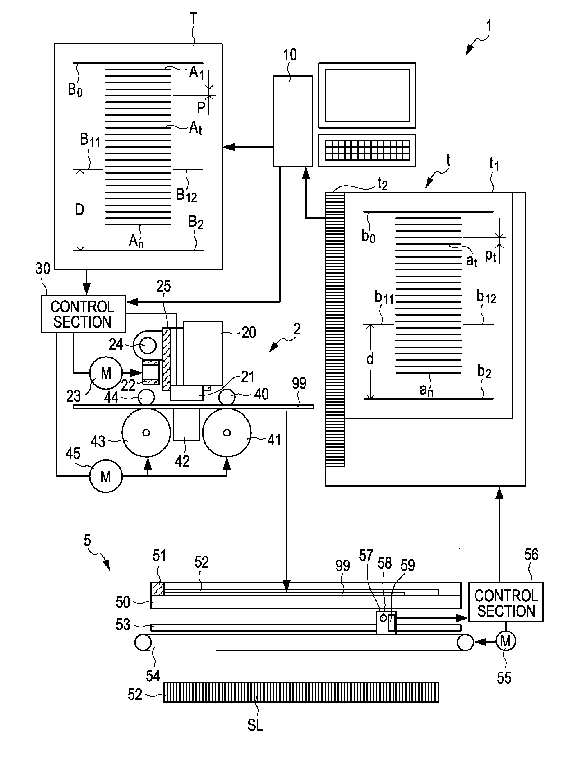
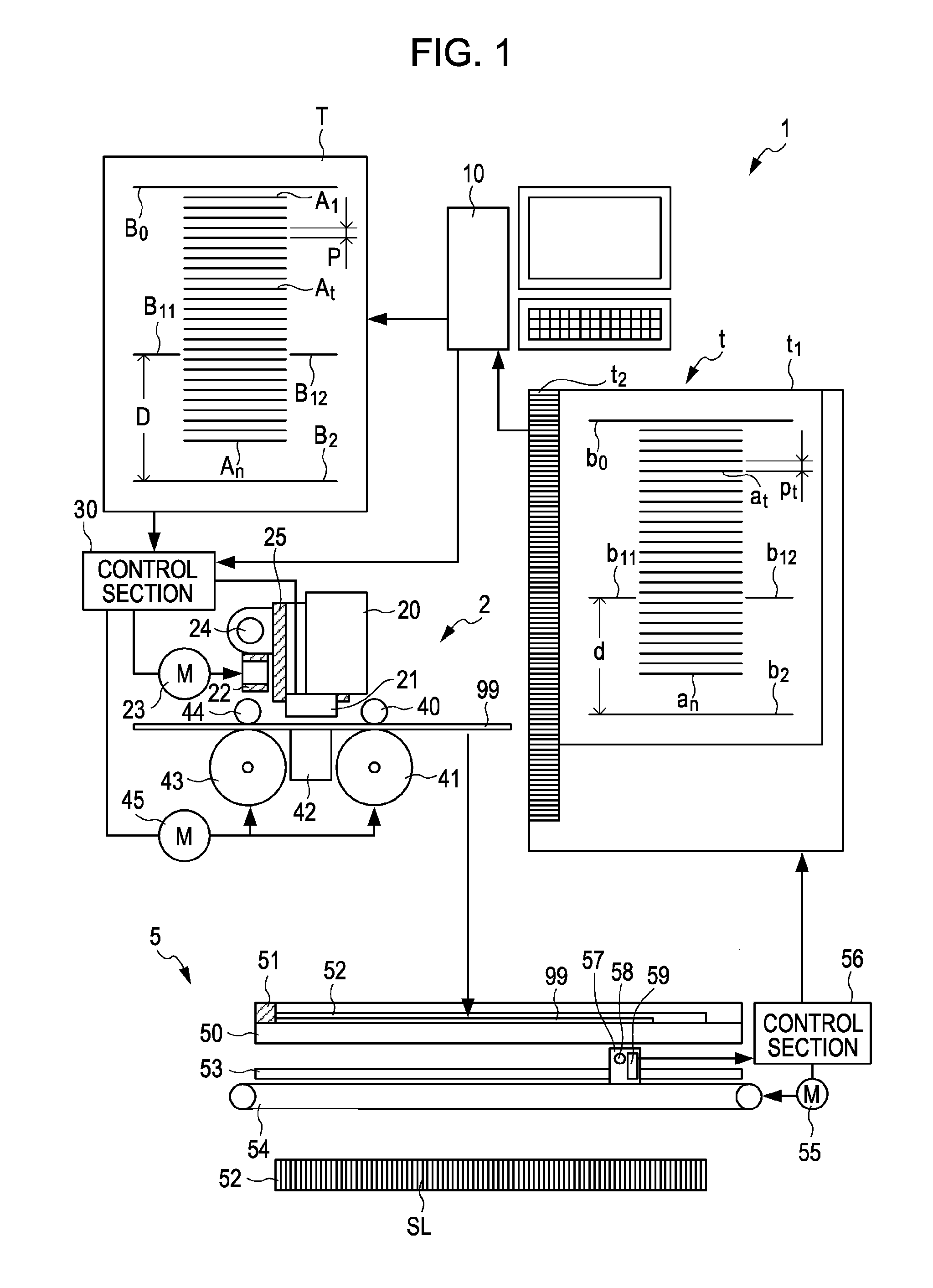
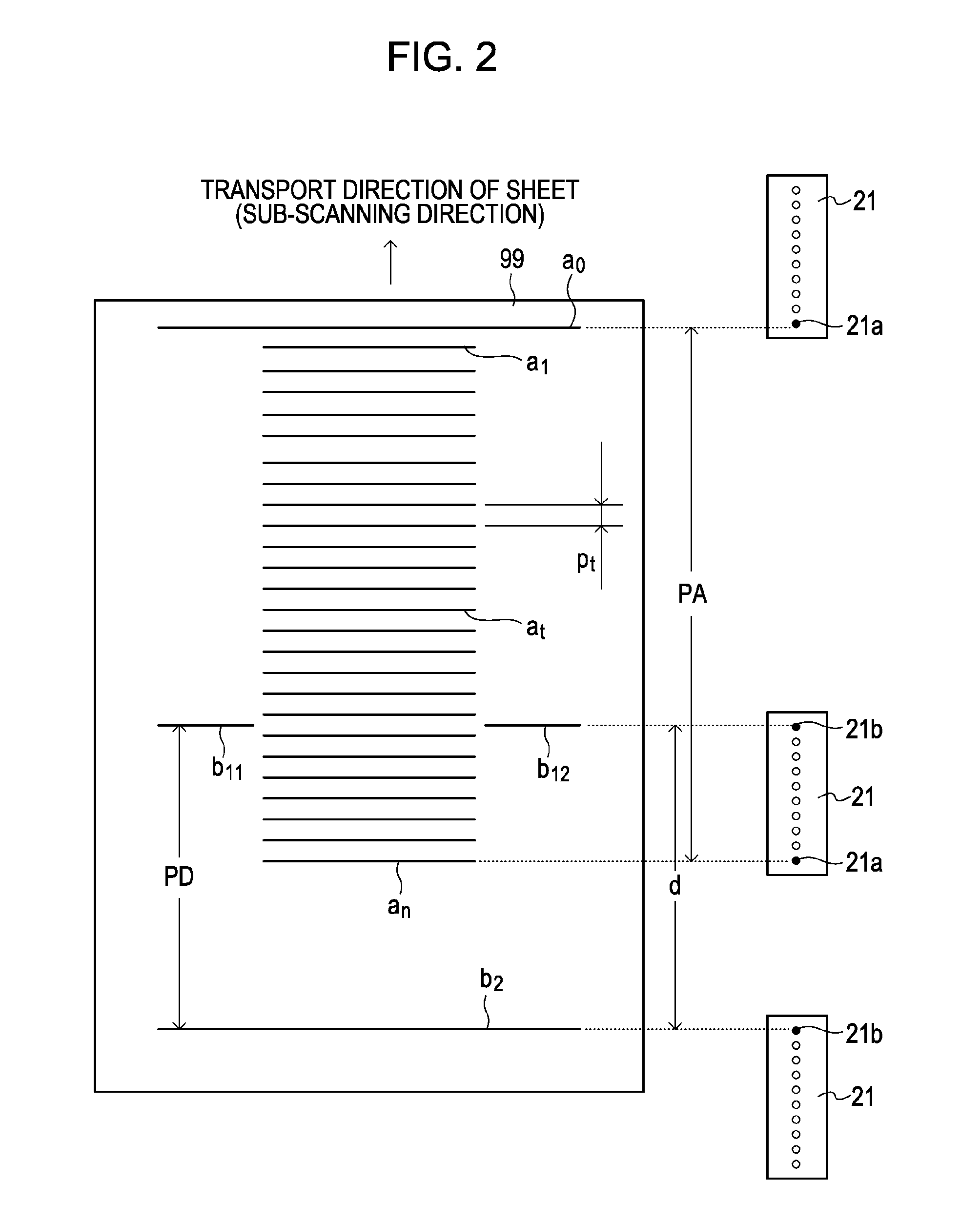
[0011]In the above aspect of the invention, with respect to an AC component of a transport error in a practical mode caused by an eccentricity of the transport roller, one revolution of the transport roller is divided into a plurality of angle sections and adjustment is performed for each angle section. If the test pattern related to the invention is printed, a ruled line is formed for each delimiter of the angle section. Therefore, if the test pattern related to the invention is used, the AC component of the transport error in the practical mode caused by an eccentricity of the transport roller can be predicted from the arrangement interval of the ruled lines. That is, according to the above aspect of the invention, by detecting the arrangement interval of a plurality of ruled lines formed on the medium, it is possible to accurately predict the AC component of the transport error in the practical mode except for a DC component caused by slippage between the transport roller and the medium. Here, also when forming a plurality of ruled lines on the medium, slippage between the transport roller and the medium can be generated. However, under the condition that the amount of slippage is sufficiently suppressed, certain slippage may be regarded as being generated even in intermittent transport corresponding to different angle sections. For example, it is acceptable if the average of a difference between the average of the arrangement intervals of the printed ruled lines and a reference interval (an arrangement interval as a control amount) of the ruled lines is regarded as the amount of slippage. However, slippage between the medium and the transport roller is irregularly generated. Therefore, transport corresponding to the same angle section is adjusted on the basis of the average value of a plurality of arrangement intervals corresponding to the same angle section. That is, according to the aspect of the invention, by accurately predicting the AC component of the transport error, thereby adjusting transport, it is possible to increase transport accuracy of the medium in the image forming apparatus.
[0016]In the intermittent transport, the larger the absolute value of the angular acceleration of the transport roller becomes, the larger a difference (this difference is called the amount of slippage) between the length of the surface of the transport roller passing a contact point between the transport roller and the medium per unit time and a progress distance of the medium per unit time becomes. If the test pattern which is formed according to the above aspect of the invention is used, the AC component of the transport error in the practical mode caused by the eccentricity of the transport roller can be predicted from an arrangement interval of a plurality of ruled lines which is formed on the medium by repeating the intermittent transport having slower acceleration than that in the practical mode. That is, according to the above aspect of the invention, by detecting the arrangement interval of a plurality of ruled lines formed on the medium, it is possible to accurately predict the AC component of the transport error in the practical mode except for the DC component caused by slippage between the transport roller and the medium.

Problems solved by technology

If the transport roller is eccentrically disposed, a rotary shaft of a motor which drives the transport roller is eccentrically disposed due to a mounting error on a frame, the circumferential length of the transport roller has variation, or the medium slips with respect to the transport roller, an error is generated in a transport distance of the medium which is derived from the angle of rotation of the transport roller.
On the other hand, the DC component of the transport error which is generated in the practical mode due to slippage between the medium and the transport roller cannot be accurately predicted if the slippage between the transport roller and the medium which is generated by transport in the practical mode is not reproduced.
Therefore, according to the methods disclosed in JP-A-2002-273956, JP-A-2008-302659, and JP-A-2008-260168, there is a problem in that accuracy of detecting the AC component and the DC component of the transport error is low.
However, slippage of the medium which is generated by intermittent transport in the respective modes is not constant.
However, slippage between the medium and the transport roller is irregularly generated.
The transport error which is generated in this state is a transport error of the transport roller disposed upstream of the nozzle.
The transport error which is generated in this state is a transport error of the transport roller disposed downstream of the nozzle.
If the contact state of the transport roller with the medium during the period of printing the test pattern is different from that in the practical mode, the arrangement interval of the ruled lines cannot serve as the basis for accurately predicting the transport error in the practical mode.

Method used


Image

  • Transport adjustment method, transport adjustment system, and transport adjustment program
  • Transport adjustment method, transport adjustment system, and transport adjustment program
  • Transport adjustment method, transport adjustment system, and transport adjustment program

Examples


Embodiment Construction

[0028]Hereinafter, embodiments of the invention will be described with reference to the accompanying drawings. Further, in each drawing, corresponding constituent elements are denoted by the same symbol and an overlapping description is omitted.

1. Overview

[0029]The configuration of a transport adjustment system 1 as one embodiment of the invention is shown in FIG. 1. The transport adjustment system 1 is constituted by a PC (Personal Computer) 10, a printer 2 connected to the PC 10, and a scanner 5. The transport adjustment system 1 is a system for adjusting an operation in which the printer 2 transports one of various sheets as a printing medium. That is, the PC 10 outputs test pattern data T to the printer 2, thereby making the printer 2 form a test pattern on rolled paper 99. The scanner 5 reads the test pattern formed on the rolled paper 99 and supplies scan data t representing the test pattern to the PC 10. The PC 10 detects distortion of a sub-scanning direction with respect to...


PUM


Abstract

A transport adjustment method of adjusting transport of an image forming apparatus which includes a transport roller that transports a medium in a sub-scanning direction and a plurality of nozzles lining up in the sub-scanning direction and repeats the transport and main scanning of moving the plurality of nozzles in a main scanning direction, for each angle section formed by dividing one revolution of the transport roller into a plurality of angle sections, the method including: printing, by forming a ruled line by the main scanning every time the transport corresponding to the angle section is carried out, a test pattern in which a plurality of ruled lines is arranged; detecting an arrangement interval of the printed ruled lines; and adjusting the transport corresponding to the same angle section on the basis of the average value of a plurality of arrangement intervals corresponding to the same angle section.

Description

BACKGROUND[0001]1. Technical Field[0002]The present invention relates to a technique of adjusting transport of a medium by an image forming apparatus which repeats the transport of the medium in a sub-scanning direction and the discharge of ink involving nozzle movement in a main scanning direction.[0003]2. Related Art[0004]Hitherto, in an image forming apparatus such as an ink jet printer, a sheet-like medium such as paper or film has been transported by driving a transport roller. If the transport roller is eccentrically disposed, a rotary shaft of a motor which drives the transport roller is eccentrically disposed due to a mounting error on a frame, the circumferential length of the transport roller has variation, or the medium slips with respect to the transport roller, an error is generated in a transport distance of the medium which is derived from the angle of rotation of the transport roller. In general, in such an error, an AC component which is a transport error that perio...

Claims


Application Information

Patent Timeline
IPC IPC(8): B41J29/38
CPCB41J11/46
Inventor NAKANO, TATSUYAYOSHIDA, MASAHIKOTOKUNAGA, MICHIAKIYOSHIDA, TAKESHI
Owner SEIKO EPSON CORP
Learn More