Surgical instrument

Active Publication Date: 2012-04-05
ENDOCONTROL
View PDF4 Cites 19 Cited by
  • Summary
  • Abstract
  • Description
  • Claims
  • Application Information

AI Technical Summary

Benefits of technology

[0021]According to the proposed invention, the enabled direct transmission produces an infinite rotation of the forceps about its own axis, without having to modify the position of the axis of the forceps, or reconfiguring movements or using a clutch system. All rotations are maintained and/or actuated independently. Further, all rotations may be actuated simulta

Problems solved by technology

However, the main limitation is the decrease in dexterity associated with a remote access by long instruments.
In particular, with conventional laparoscopic rigid instruments, it is impossible to bend the distal end of the instrument to orient the forceps optimally relative to the practitioner.
This is a major application limitation of laparoscopic surgical tools for surgical procedures.
During some interventions, positioning the points of incision relative to the operating site is such that it is not possible to align the axis of the forceps with the edges to be sutured when using rigid instruments, substantia

Method used


Image

  • Surgical instrument
  • Surgical instrument
  • Surgical instrument

Examples


first embodiment

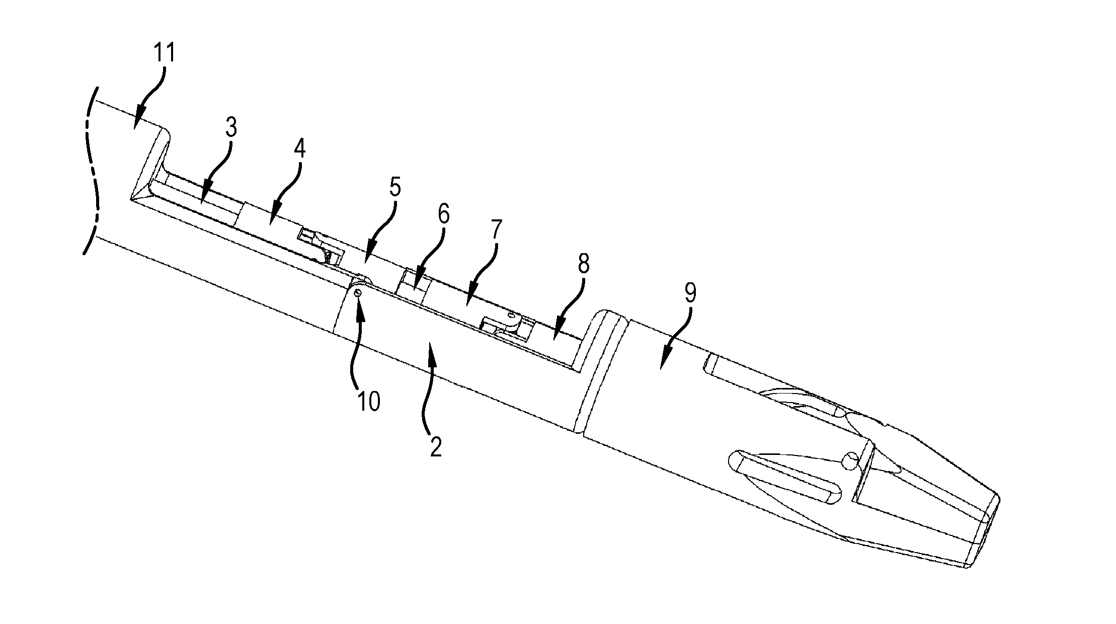
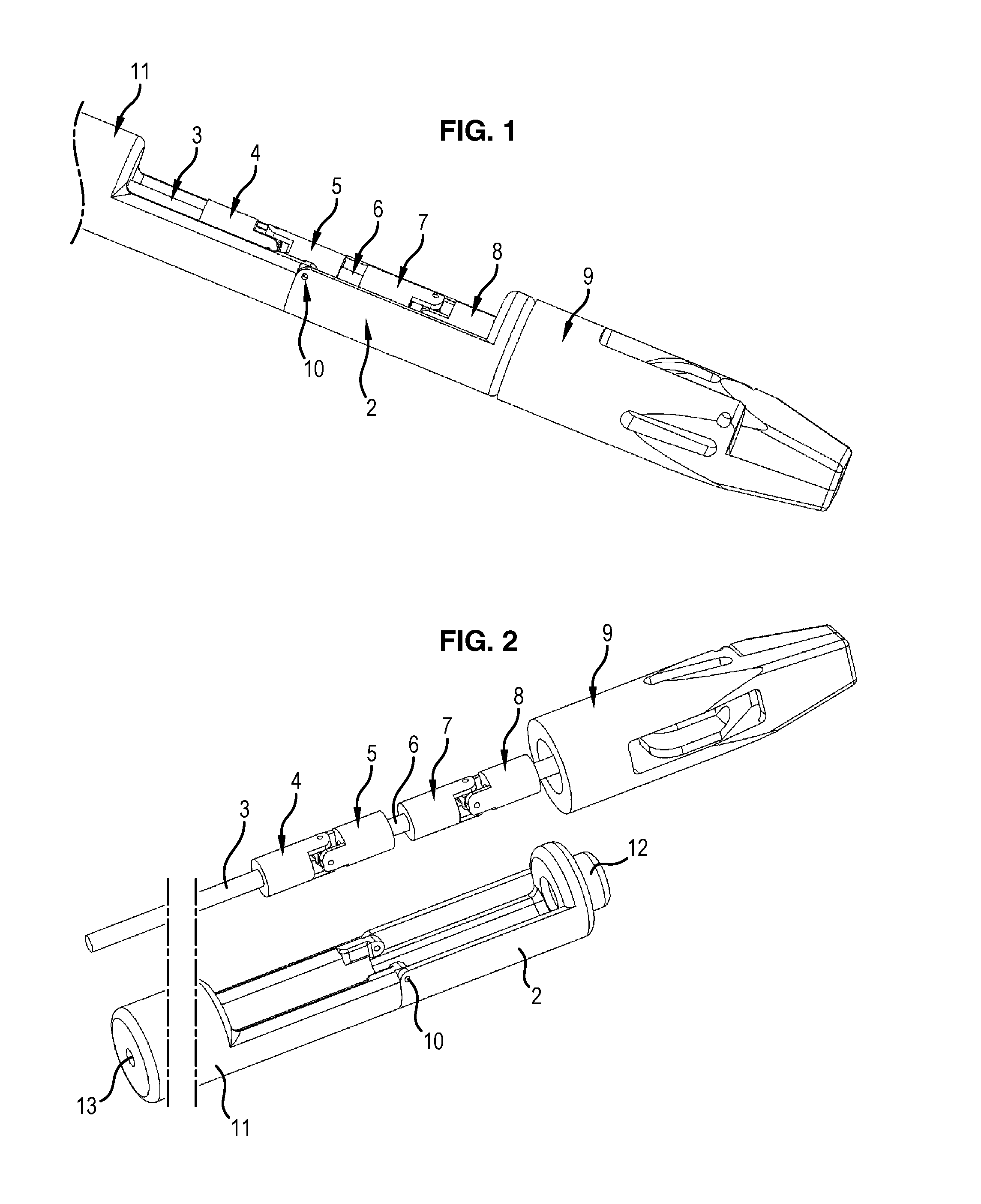
[0051]In reference to FIGS. 1 and 2, we will describe a surgical instrument according to the invention.

[0052]FIG. 1 illustrates the distal part of a surgical instrument 1 according to a first embodiment of the invention. The surgical instrument 1 comprises an elongated arm 11, here in a cylindrical revolution shape according to a longitudinal axis (not shown). The elongated arm is hollow and has, on a distal part, an opening on a semi-circumference terminating longitudinally via linking means comprising an axis 10 substantially orthogonal to the longitudinal axis of the elongated arm 11 and extending according to a diameter of a section of said elongated arm 11. These linking means connect the elongated arm to a distal end 2 comprising, in this respect, complementary linking means. This forms a pivot joint between the elongated arm 11 and the distal end 2. The distal end 2 here is hollow, cylindrical in revolution in shape about an axis and open on a semi-circumference approximately...

second embodiment

[0058]In reference to FIGS. 4 and 5, a surgical instrument 100 according to the invention will now be described. The surgical instrument 100 according to the invention comprises an elongated arm 111, here cylindrical in revolution in shape according to a longitudinal axis (not shown). The elongated arm 111 distally comprises a base linking element 101 comprising an axis 110 substantially perpendicular to the longitudinal axis of the elongated arm 111. The elongated arm 111 further comprises a second linking element 102 comprising a bore 112 at a proximal end and an axis 110 similar to the axis 110 of the base linking element 101 and situated at a distal end of the second linking element 102. The second linking element 102 is mounted in rotation on the base linking element 101 by cooperation of the axis 110 of the base linking element 101 and the bore 112 of the second linking element 102, thus forming a pivot joint. The elongated arm 111 further comprises a third linking element 105...

third embodiment

[0062]In reference to FIGS. 8 and 9, a surgical instrument 200 according to the invention will now be described. The surgical instrument 200 according to the invention comprises an elongated arm 207, here cylindrical in revolution in shape according to a longitudinal axis (not shown). The elongated arm 207 is hollow and distally comprises a base linking element 201 hollow, comprising two lugs extending in the extension of the elongated arm 207 and opposite one another to define an axis 210 substantially perpendicular to the longitudinal axis of the elongated arm 207. The elongated arm 207 further comprises second hollow linking elements 202, 203 (also called intermediate linking elements), comprising two lugs extending in the extension of said second linking elements 202, 203 and opposite one another to define an axis 210 similar to the axis 210 of the base linking element 201 and located at a distal end of the second linking elements 202, 203. The second linking element 202 is moun...


PUM


Abstract

The invention relates to a surgical instrument (100; 200) comprising:
    • an elongated arm (111; 207) according to a longitudinal axis and having a distal end (105; 204) mounted with a pivot joint on the elongated arm according to an axis substantially orthogonal to the longitudinal axis;
    • a drive shaft (103; 3), substantially coaxial with the elongated arm, comprising means forming a universal joint (104; 206) facing the pivot joint; and,
    • distal tool (9) securely fastened on the drive shaft and rotatively mounted on and in the extension of the distal end of the elongated arm, such that the distal tool has two rotational degrees of freedom, distinct and independent of each other, one being around an axis substantially perpendicular to the longitudinal axis of the elongated arm and the other being around an axis substantially collinear to an own axis of the distal tool, characterised in that the means forming a universal joint comprise a flexible drive sleeve (104; 206).

Description

FIELD OF THE INVENTION[0001]The invention relates to a surgical instrument designed for endoscopic or laparoscopic surgical operations.TECHNICAL BACKGROUND[0002]Within the scope of minimally-invasive surgery, such as endoscopic or laparoscopic surgery, access to the operating site is made via small incisions in the body of the patient (such as the abdomen or thorax), in which the practitioner places a canula formed by a tube whereof the diameter varies from 3 to 15 mm, via which the practitioner can insert into the body of the patient either an endoscope for obtaining a video image on a monitor, or long and fine instruments for performing a procedure at the operating site.[0003]The majority of existing instruments is constituted by a fine (typically around 5 mm in diameter) and rigid elongated body (typically around 30 cm long). The proximal end of the instrument comprises a grip handle for the practitioner and the distal end of the instrument is often fitted with a forceps or sciss...

Claims


Application Information

Patent Timeline
IPC IPC(8): A61B17/00
CPCA61B17/29A61B2017/003A61B2017/00309A61B2017/00323A61B2017/2947A61B2017/2905A61B2017/2908A61B2017/2927A61B2017/2929A61B2017/0069
Inventor PAIK, JAMIEMOREL, GUILLAUMEVIDAL, CLEMENTHENRI, PATRICK
Owner ENDOCONTROL
Why Eureka
Try Eureka