Remote controller setting module, television and remote control command setting method thereof

Inactive Publication Date: 2012-04-12
CAL COMP ELECTRONICS +1
View PDF9 Cites 2 Cited by
  • Summary
  • Abstract
  • Description
  • Claims
  • Application Information

AI Technical Summary

Benefits of technology

[0006]The objective of the present invention is to provide a remote controller setting module, television and remote control command setting method thereof. The remote controller setting module of the present invention can be applied to an electronic device thereby allowing a user to reconfigure the electronic device in order to identify the button command of different remote

Problems solved by technology

There exists a lot of infrared encoding and decoding methods, and currently available products using remote controller may take different coding/decoding (codec) approaches, so the remote controller thereof can not be shared.
Hence, in case a user unfortunately lost the remote controller, he/she would have to search for it with great efforts; nevertheless, after

Method used


Image

  • Remote controller setting module, television and remote control command setting method thereof
  • Remote controller setting module, television and remote control command setting method thereof
  • Remote controller setting module, television and remote control command setting method thereof

Examples


first embodiment

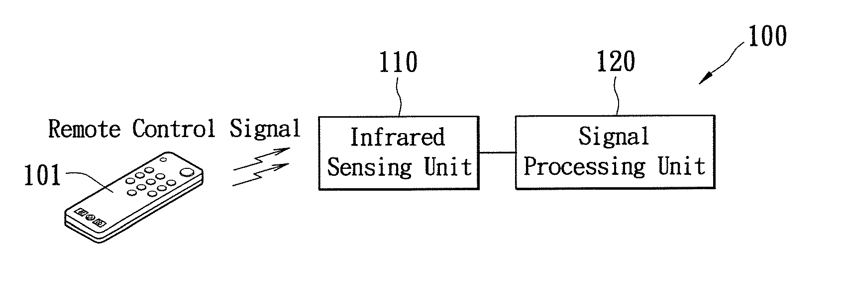
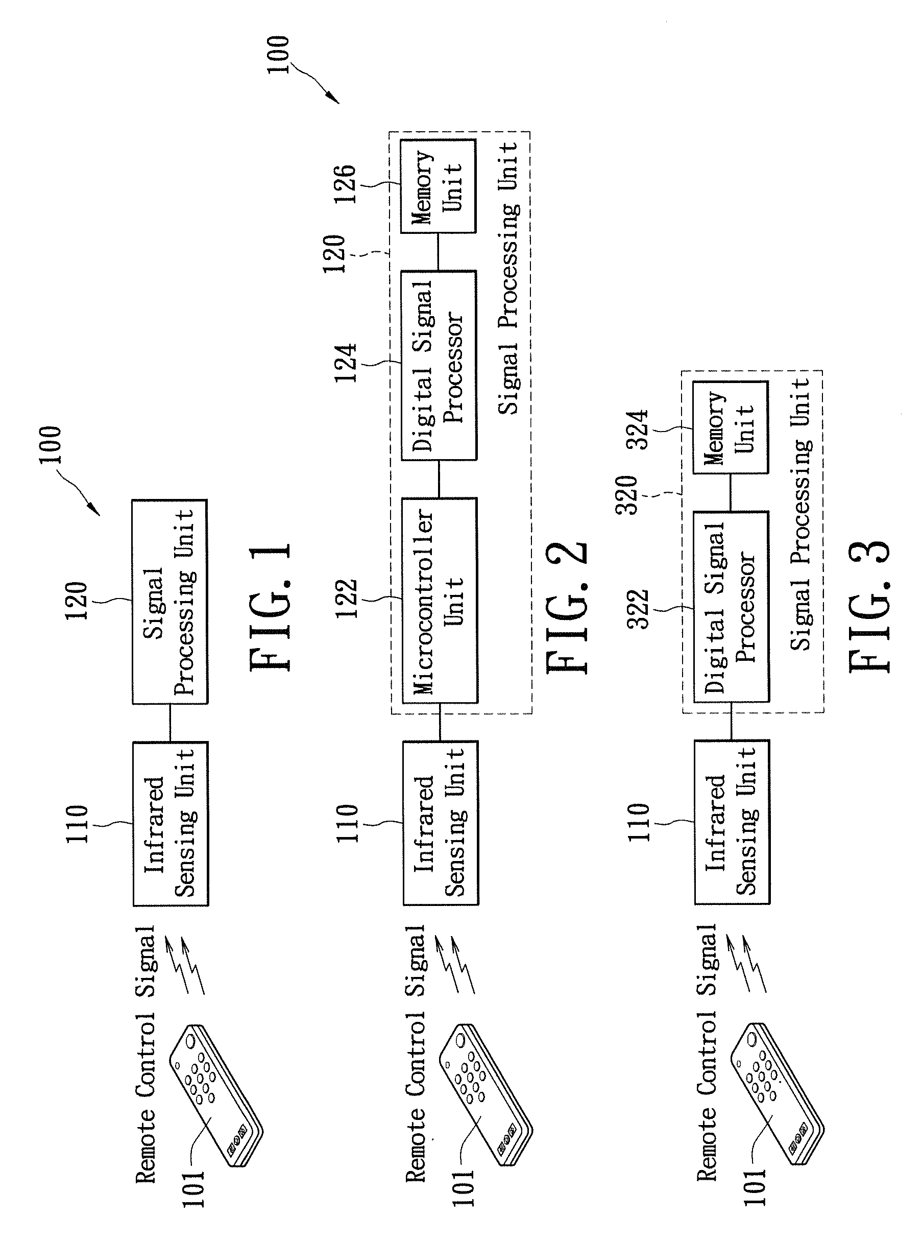
[0017]FIG. 1 shows a functional block diagram of a remote controller setting module according to a first embodiment of the present invention. Herein the remote controller setting module 100 comprises an infrared sensing unit 110 and a signal processing unit 120. The infrared sensing unit 110 is used to receive a remote control signal emitted by a remote controller 101 and identify the signal waveform corresponding to such a remote control signal. The signal processing unit 120 is coupled to the infrared sensing unit 110 and used to set the button command of the waveform corresponding to the remote control signal. In the present embodiment, the remote controller 101 can be, for example, an infrared remote controller, the remote control signal thereby emitted can be an infrared signal generated as a button on the remote controller 101 being pressed down.

[0018]The infrared sensing unit 110 can be implemented by using the infrared receiver diode or photo-transistor. A serial connection ...

second embodiment

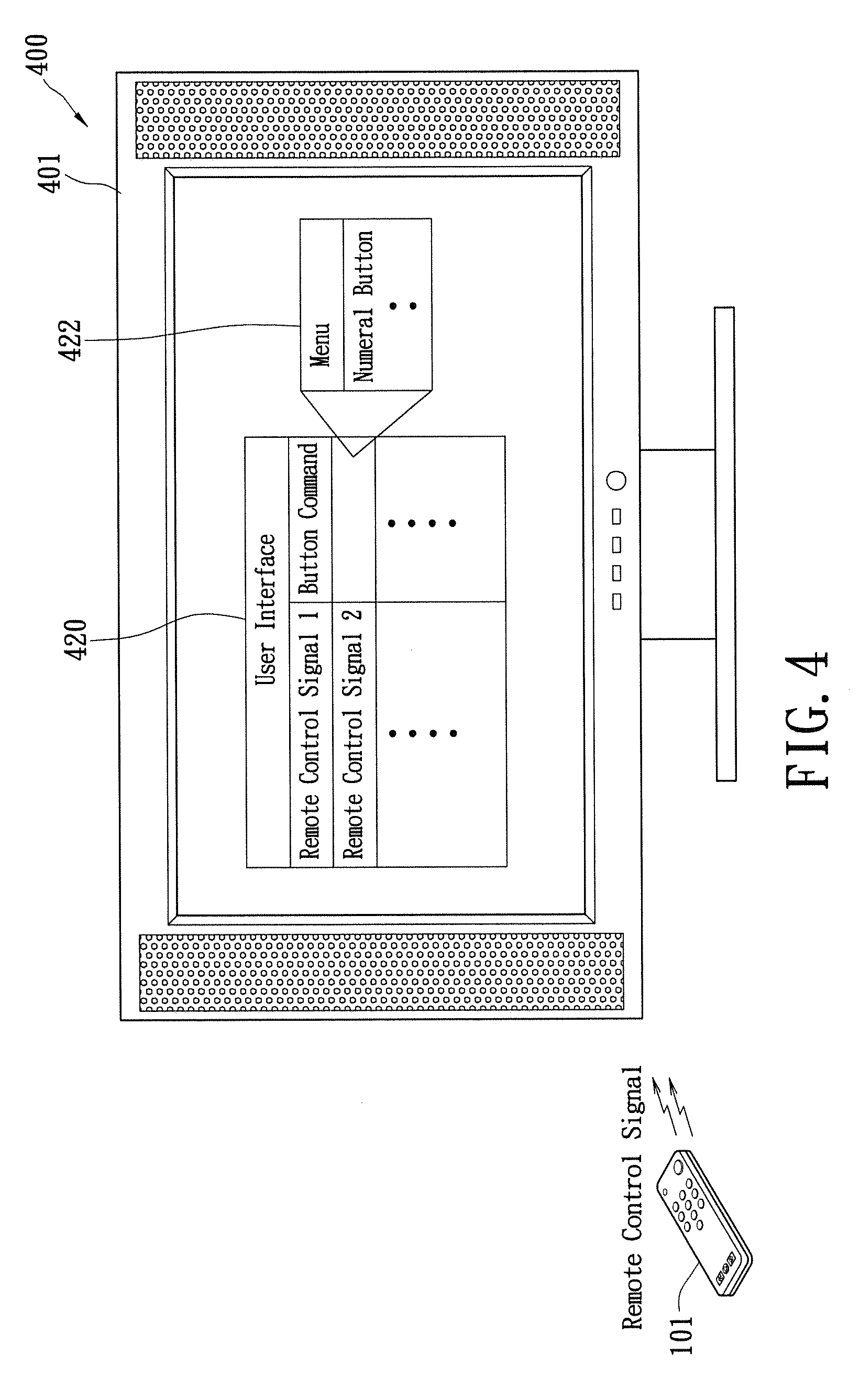
[0026]From the previously illustrated embodiment, a remote control command setting method can be deduced which is suitable for setting a button command to correspond to a remote control signal emitted by a remote controller. Refer collectively to FIGS. 1-5, and in particular FIG. 5 shows a flowchart of the remote control command setting method according to a second embodiment of the present invention which comprises the following steps: initially, providing a user interface (STEP S510), as shown in FIG. 4; next, presenting a prompt through the user interface to ask a user to press down a button on the remote controller so as to generate a remote control signal (i.e., an infrared signal) (STEP S520); subsequently, determining whether the remote control signal is sensed (STEP S530); if the remote control signal is sensed, then identifying the signal waveform of the received remote control signal (STEP S540); afterward, presenting a menu via the user interface to the user thereby selec...


PUM


Abstract

A remote control setting module which is suitable to be installed in an electronic apparatus to set a button command corresponding to a remote control signal from a remote controller is disclosed. The remote control setting module includes an infrared sensing unit and a signal processing unit. The infrared sensing unit receives the remote control signal from the remote controller and then identifies a signal waveform corresponding to remote control signal. The signal processing unit is coupled to the infrared sensing unit and used for setting the button command to correspond to the received signal waveform.

Description

BACKGROUND OF THE INVENTION[0001]1. Field of the Invention[0002]The present invention relates to a receiving module in an infrared remote controller; in particular, to a remote controller setting module, electronic device and remote control command setting method thereof.[0003]2. Description of Related Art[0004]The wavelength of infrared is between microwave and visible light which ranges from about 770 nm to approximately 1 mm. As the way it is referenced, infrared is located outside of red light on the optical spectrum, demonstrating significant thermal effects and easily absorbed by objects, thus usually applied as a heat source. Infrared is comprehensively employed in various fields, such as communication, detection, medical care, military and so forth. In people's daily lives, it is commonly utilized as an infrared remote controller for a television.[0005]There exists a lot of infrared encoding and decoding methods, and currently available products using remote controller may t...

Claims


Application Information

Patent Timeline
IPC IPC(8): H04N5/44G08C19/16H04B10/00
CPCG08C23/04G08C2201/20H04N21/42221H04N2005/4435H04N21/42204H04N5/4403H04N21/42226
Inventor LEE, HWAI-CHIH
Owner CAL COMP ELECTRONICS
Why Eureka
Try Eureka