Suspension board with circuit

Inactive Publication Date: 2012-04-12
NITTO DENKO CORP
View PDF5 Cites 52 Cited by
  • Summary
  • Abstract
  • Description
  • Claims
  • Application Information

AI Technical Summary

Benefits of technology

[0010]It is an object of the present invention to provide a suspension board with circuit that is capable of mounting a slider so that the slider is capable of relatively moving with respect to a conductive region, adjusting the position and the angle of a magnetic head finely, achieving miniaturization and high density arrangement of a conductive layer, and preventing damage to the conductive layer.
[0026]In the suspension board with circuit, the pedestal is formed so as to extend along the moving direction of the slider, so that the moving slider is supported reliably and therefore, the spacing between the opposing region and the slider in the thickness direction can be ensured reliably.

Problems solved by technology

However, when the trace is disposed so as to detour around the head slider, it is difficult to achieve miniaturization of the suspension board with circuit and high density arrangement of the trace.
On the other hand, when the trace is disposed so as to be overlapped with the head slider in the thickness direction, there is a disadvantage that the end portion of the head slider frictionally slides against the trace at the time of the rotation of the head slider, so that the trace is damaged.

Method used


Image

  • Suspension board with circuit
  • Suspension board with circuit
  • Suspension board with circuit

Examples


Embodiment Construction

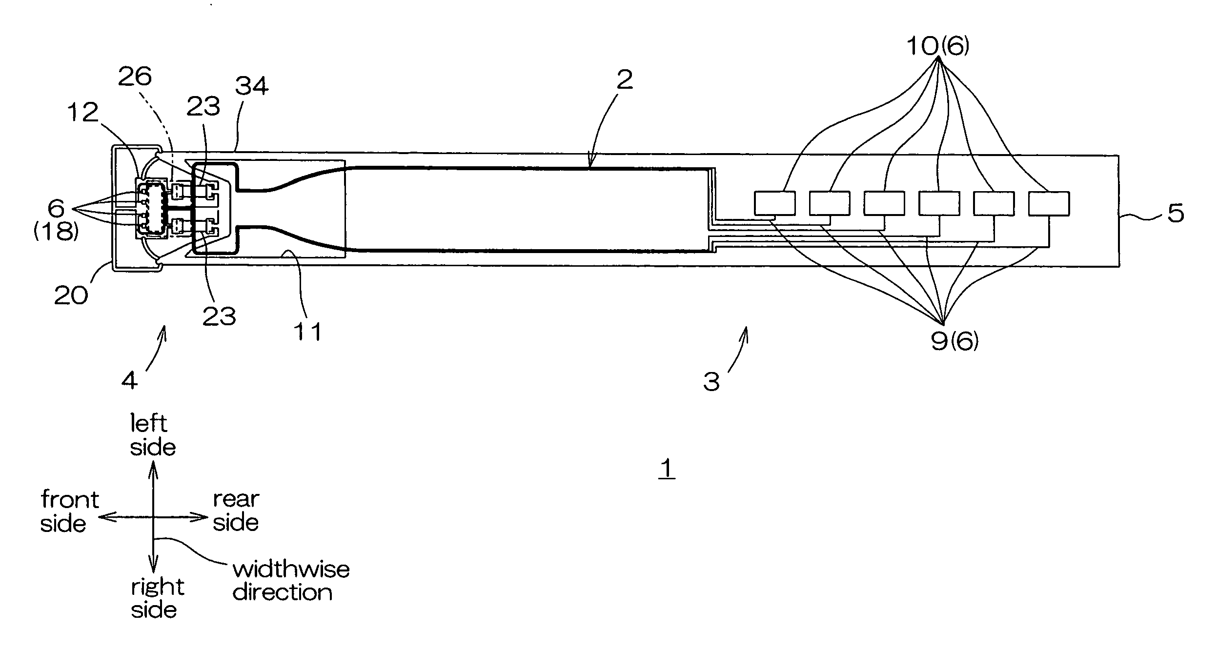
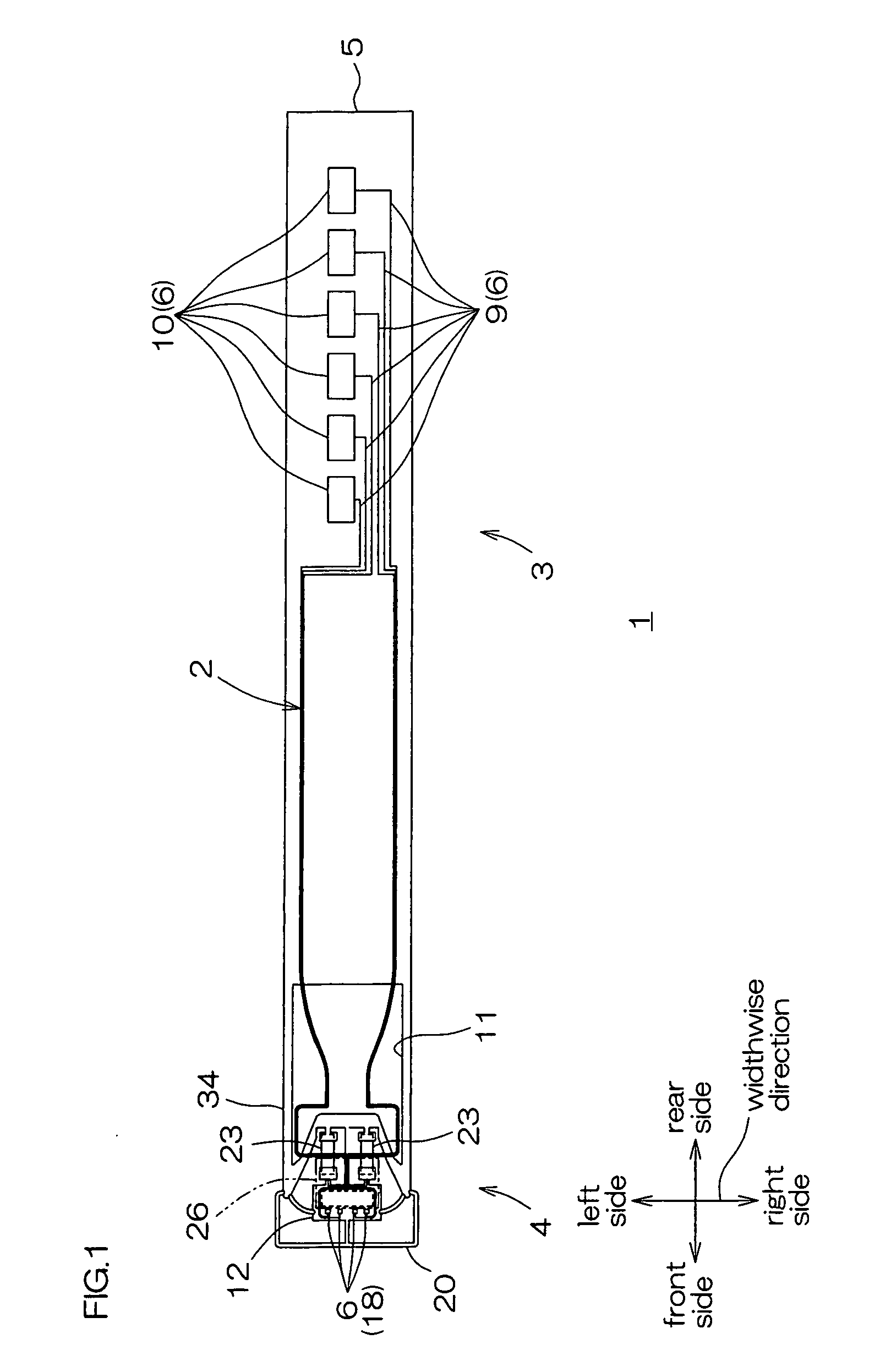
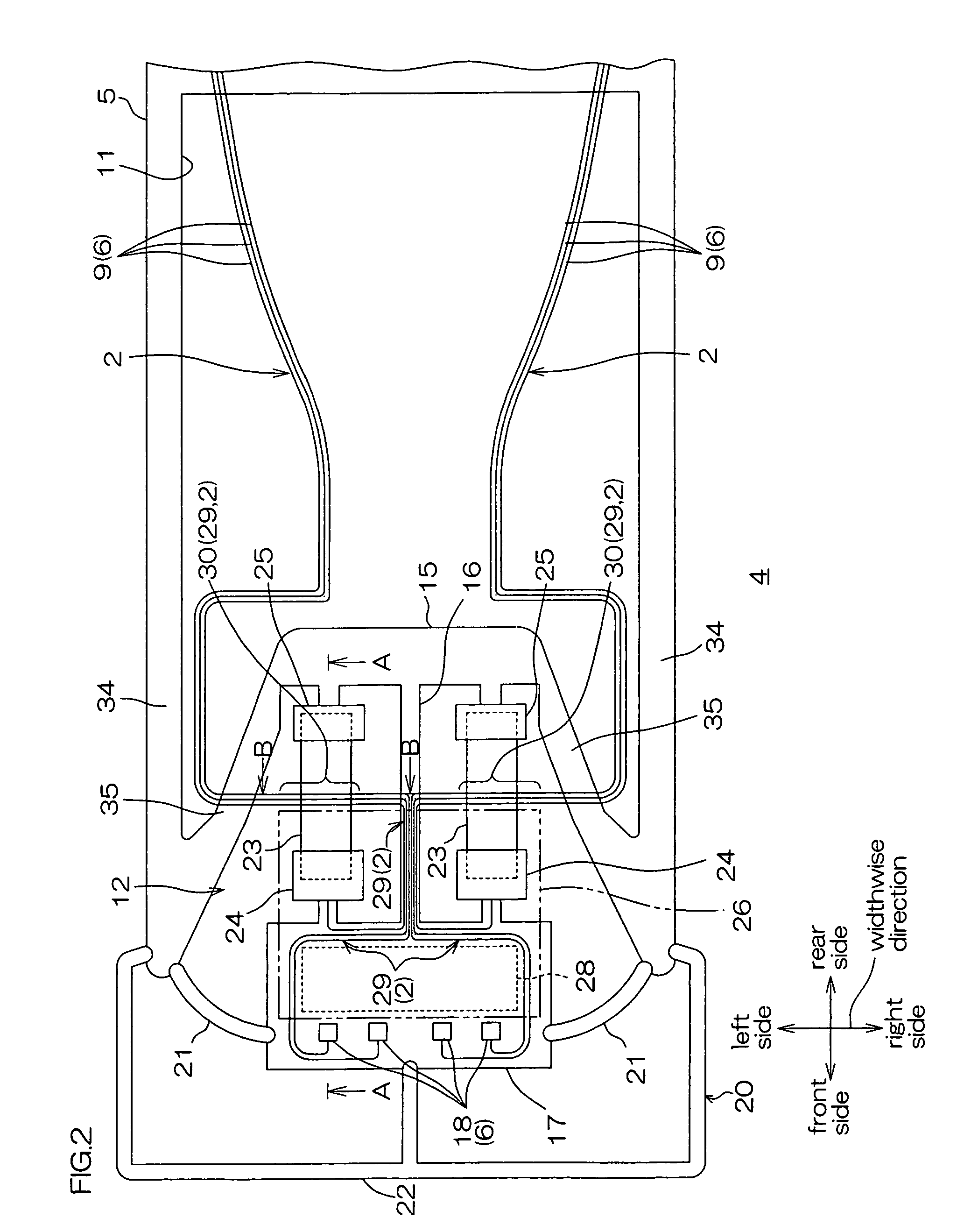
[0064]FIG. 1 shows a plan view of one embodiment (embodiment in which a thin-walled region is provided) of a suspension board with circuit of the present invention. FIG. 2 shows an enlarged plan view of a gimbal portion of the suspension board with circuit shown in FIG. 1. FIGS. 3 and 4 show sectional views, each taken along the line A-A and the line B-B of the gimbal portion shown in FIG. 2. FIGS. 5 and 6 each show a plan view and a sectional view illustrating a state where a stage of the gimbal portion is swung shown in FIG. 2. FIG. 7 shows process drawings for describing a method for producing the suspension board with circuit.

[0065]In FIGS. 1, 2, and 5, an insulating base layer 7 and an insulating cover layer 8 to be described later are omitted so as to clearly show the relative arrangement of a conductive layer 6 and a slider 26 to be described later.

[0066]In FIGS. 1 and 2, a suspension board with circuit 1 is mounted with the slider 26 (phantom lines in FIG. 2 and solid lines ...


PUM


Abstract

A suspension board with circuit includes a conductive region in which a conductive layer is formed and a mounting region for mounting a slider on which a magnetic head that is electrically connected to the conductive layer is mounted. The mounting region mounts the slider so that the slider is capable of relatively moving with respect to the conductive region, and the conductive region includes an opposing region that is opposed to the slider in the thickness direction at the time of the relative movement of the slider with respect to the conductive region and a damage preventing portion for preventing damage to the opposing region by the slider.

Description

CROSS-REFERENCE TO RELATED APPLICATION[0001]The present application claims the benefit of U.S. Provisional Application No. 61 / 344,833 filed on Oct. 20, 2010, and claims priority from Japanese Patent Applications No. 2010-227592 filed on Oct. 7, 2010 and No. 2011-155499 filed on Jul. 14, 2011, the contents of which are hereby incorporated by reference into this application.BACKGROUND OF THE INVENTION[0002]1. Field of the Invention[0003]The present invention relates to a suspension board with circuit, to be specific, to a suspension board with circuit that is used in a hard disk drive.[0004]2. Description of Related Art[0005]Conventionally, it has been known that a microactuator is provided in a suspension board with circuit on which a magnetic head is mounted so as to adjust the position and the angle of the magnetic head finely.[0006]There has been proposed, for example, a head gimbal assembly including a tongue portion that has a stage and in which a trace is formed, a head slider ...

Claims


Application Information

Patent Timeline
IPC IPC(8): G11B5/60
CPCG11B5/4826G11B5/486G11B5/4853G11B5/484G11B5/483
Inventor OHSAWA, TETSUYA
Owner NITTO DENKO CORP
Why Eureka
Try Eureka