Thermal battery for power systems

a technology of power system and thermal battery, which is applied in the direction of electrochemical generators, well accessories, sealing/packing, etc., can solve the problems of both short and long term effects of sub-sea blowouts, drilling for oil has always been a hazardous activity for personnel, and none, however, completely satisfies the requirements for a complete solution to the above-mentioned problems

Active Publication Date: 2012-04-12
ENSER THE
View PDF3 Cites 37 Cited by
  • Summary
  • Abstract
  • Description
  • Claims
  • Application Information

AI Technical Summary

Benefits of technology

[0038]In still another embodiment, the invention is incorporated into an improved emergency power system for providing secondary electrical power to a primary battery for a blowout preventer of a petroleum apparatus. The primary battery is connected to an electric motor for driving hydraulic apparatus to operate the blowout preventer. An isolator is interposed between the primary battery electrical power and the electric motor of the blowout preventer. A thermal battery is connected to the isolator. An actuator actuates the thermal battery to provide electrical power to the isolator upon failure of the primary battery. The isolator prevents electrical current from flowing from the thermal battery into the primary battery.

Problems solved by technology

The drilling for oil has always been a hazardous activity for the personnel at the well site, the drilling equipment, and the environment.
Although blowouts are now rather rare, both the short and long term effects of a sub-sea blowout can be catastrophic.
None, however, completely satisfies the requirements for a complete solution to the aforesaid problems.
Unfortunately, typical rechargeable batteries do not have an extended shelf life.

Method used


Image

  • Thermal battery for power systems
  • Thermal battery for power systems
  • Thermal battery for power systems

Examples


Embodiment Construction

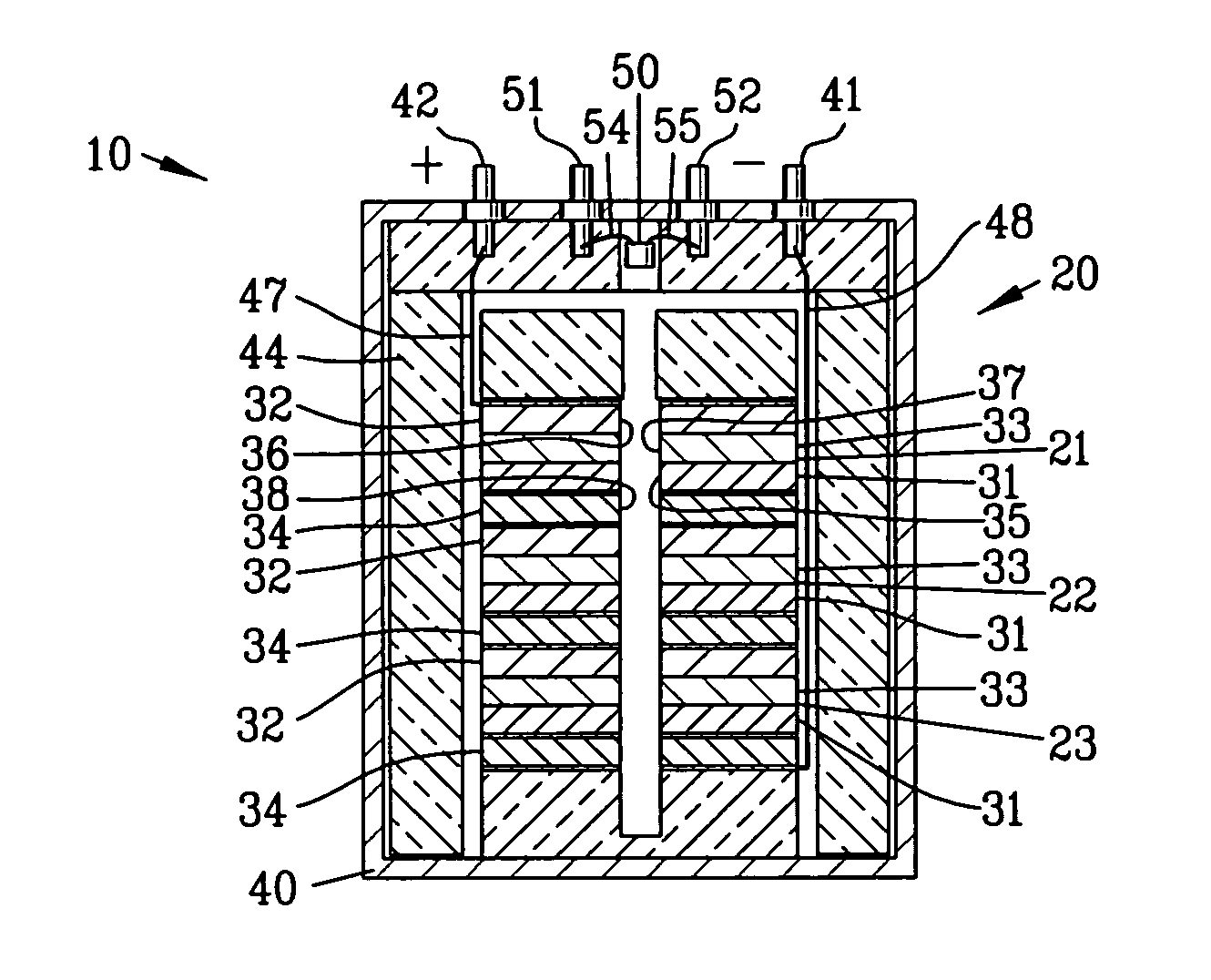
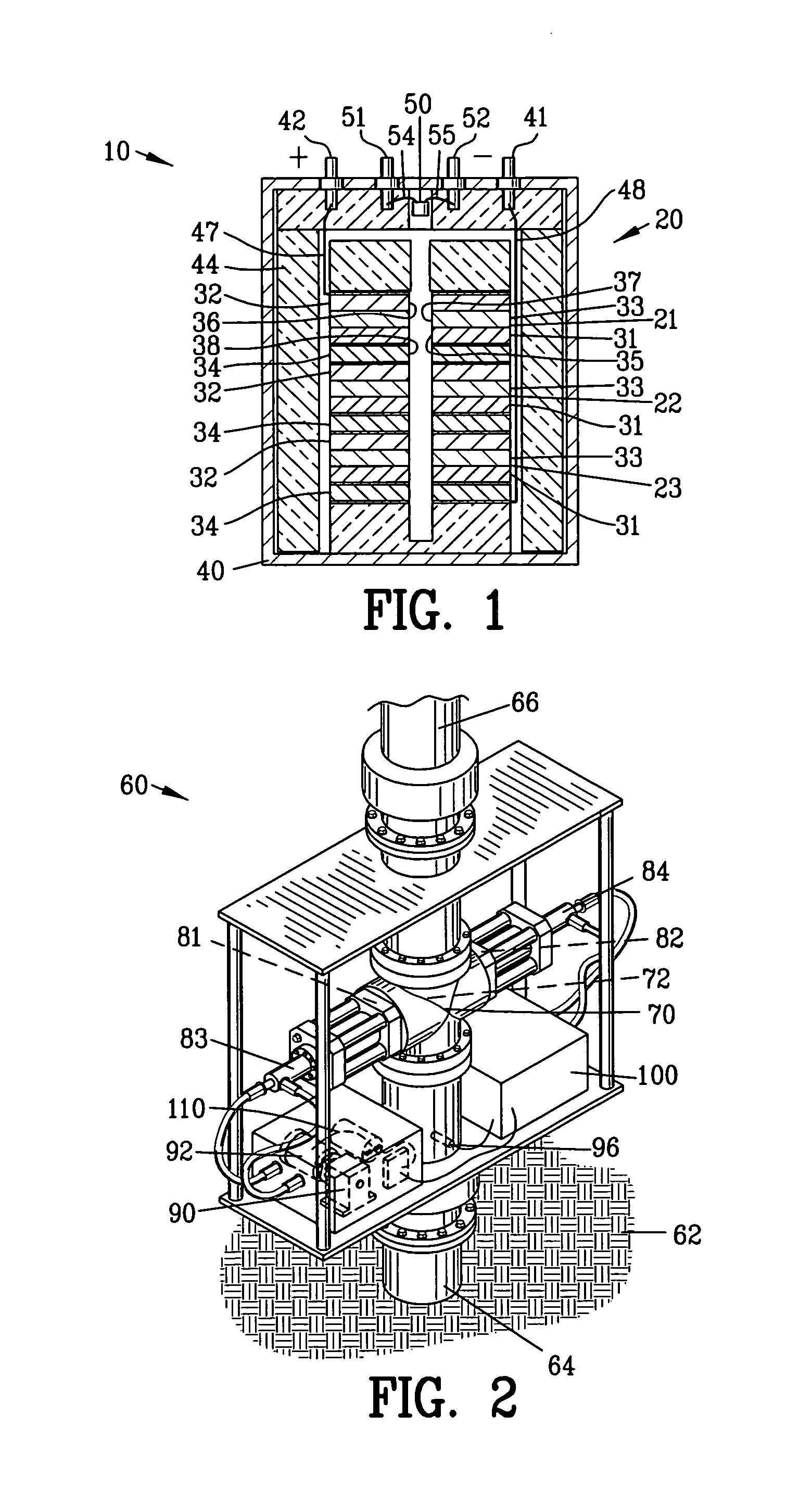
[0053]FIG. 1 is a side section view of thermal battery 10 suitable for use with the present invention. The thermal battery 10 comprises a plurality of cells 20 shown as cell 21-23 arranged in a stacked relationship. Each of the cells 21-23 comprises a plurality of battery components shown as an anode 31, a cathode 32, a separator 33 and a heat source 34. Each of the anode 31, cathode 32, separator 33 and heat source 34 is provide with holes 35-38, respectively.

[0054]The plurality of cells 20 are enclosed in a battery case 40. The battery case supports battery terminals 41 and 42. Insulation 44 is interposed between the battery case 40 and the plurality of cells 20. The plurality of cells 20 are connected to the battery terminals 41 and 42 by conductors 47 and 48.

[0055]The thermal battery 10 is provided with a squib 50 having a first and a second electrical terminal 51 and 52. The first and second electrical terminals 51 and 52 are connected to squib leads 54 and 55 located adjacent ...


PUM

PropertyMeasurementUnit
temperatureaaaaaaaaaa
electrical poweraaaaaaaaaa

Abstract

An improved emergency power system is disclosed for providing electrical power to a load such as a blowout preventer of a petroleum drilling apparatus. The improved emergency power system comprises a thermal battery having an anode and a cathode with a separator containing an electrolyte disposed therebetween. An internal heat layer is located in proximity to the separator containing the electrolyte. A squib is provided for activating the internal heat layer. The thermal battery remains dormant until the squib is energized to ignite the squib enabling the heat layer to render the electrolyte molten thereby activating battery to provide electrical power to the load. The squib may be energized remotely, mechanically or electrically.

Description

CROSS-REFERENCE TO RELATED APPLICATIONS[0001]This application claims benefit of U.S. Patent Provisional application No. 61 / 404,629 filed Oct. 6, 2010. All subject matter set forth in provisional application No. 61 / 404,629 filed Oct. 6, 2010 is hereby incorporated by reference into the present application as if fully set forth herein.BACKGROUND OF THE INVENTION[0002]1. Field of the Invention[0003]This invention relates to thermal batteries and more specifically to a thermal battery for providing standby or emergency power for a load such as a conventional blowout preventer of a petroleum drilling operation[0004]2. Description of the Related Art[0005]The drilling for oil has always been a hazardous activity for the personnel at the well site, the drilling equipment, and the environment. The uncontrolled release of crude oil and / or natural gas after failure of pressure control systems is known as a blowout. Prior to the invention of pressure control equipment in the early 20th century,...

Claims


Application Information

Patent Timeline
Patent Type & Authority Applications(United States)
IPC IPC(8): H01M6/36
CPCE21B33/064H01M16/00H01M6/36B60L1/00E21B33/02E21B33/03E21B33/06E21B33/061E21B33/062E21B33/063H01M6/38
Inventor WOOD, BRADFORD A.PUGH, JAMES K.CUBERO, JUAN A.
Owner ENSER THE
Why Eureka
Try Eureka