Screwless connection terminal

a connection terminal and screw technology, applied in the direction of electrically conductive connections, coupling device connections, electrical apparatus, etc., can solve the problems of high electrical loss, high risk of melting or fire hazards, and excessive heat generation, so as to reduce the generation of heat, and ensure the connection. the effect of mechanical and electrical connection

Active Publication Date: 2012-04-12
BALS ELEKTROTECHN
View PDF9 Cites 11 Cited by
  • Summary
  • Abstract
  • Description
  • Claims
  • Application Information

AI Technical Summary

Benefits of technology

[0008]It is therefore an object of the invention to provide an improved screwless connection terminal using clamping spring technique which can be produced in a simple and cost-effective manner and ensures a safe mechanical and electrical connection, in particular also during high current loads while simultaneously reducing the generation of heat.
[0009]Essential advantages of the invention and the individual embodiments or developments thereof are thus based on the fact that a fast, safe and controlled electrical and also mechanical connection is made possible with a conductor and larger electrical contact areas with low electrical losses are created, whereby the field of use of a screwless connection terminal according to the invention is extended with respect to its rated current and the ampacity. Furthermore, the screwless connection terminal according to the invention allows for a good heat transfer due to a lower contact resistance between the conductor to be connected and the electrical contact element in or on an electrical plug-in device or connecting device and reduces the danger of overheating or destruction of such a device. Furthermore, with respect to the mechanical fastening of a conductor to the contact element of an electrical device, the invention provides for an improvement of the mechanical tensile strength.

Problems solved by technology

As a result of this, in case of screwless connection terminals according to the prior art, there are usually high electrical contact resistances which result in excessive heat generation.
These disadvantages are increasingly experienced in particular in such cases in which high electric currents, e.g. 32 A and higher, are to be transmitted.
However, if high electrical currents flow through such a conductor terminal, the result is, besides an excessive heat generation, a high electrical loss and a high risk with respect to melting or fire hazard.
Thus, it can principally be concluded that the field of use with respect to ampacity of screwless connection terminals, the electrical contact of which is established by means of the cross-sectional area of the clamping leg of a clamp spring, is limited.

Method used


Image

  • Screwless connection terminal
  • Screwless connection terminal
  • Screwless connection terminal

Examples


Embodiment Construction

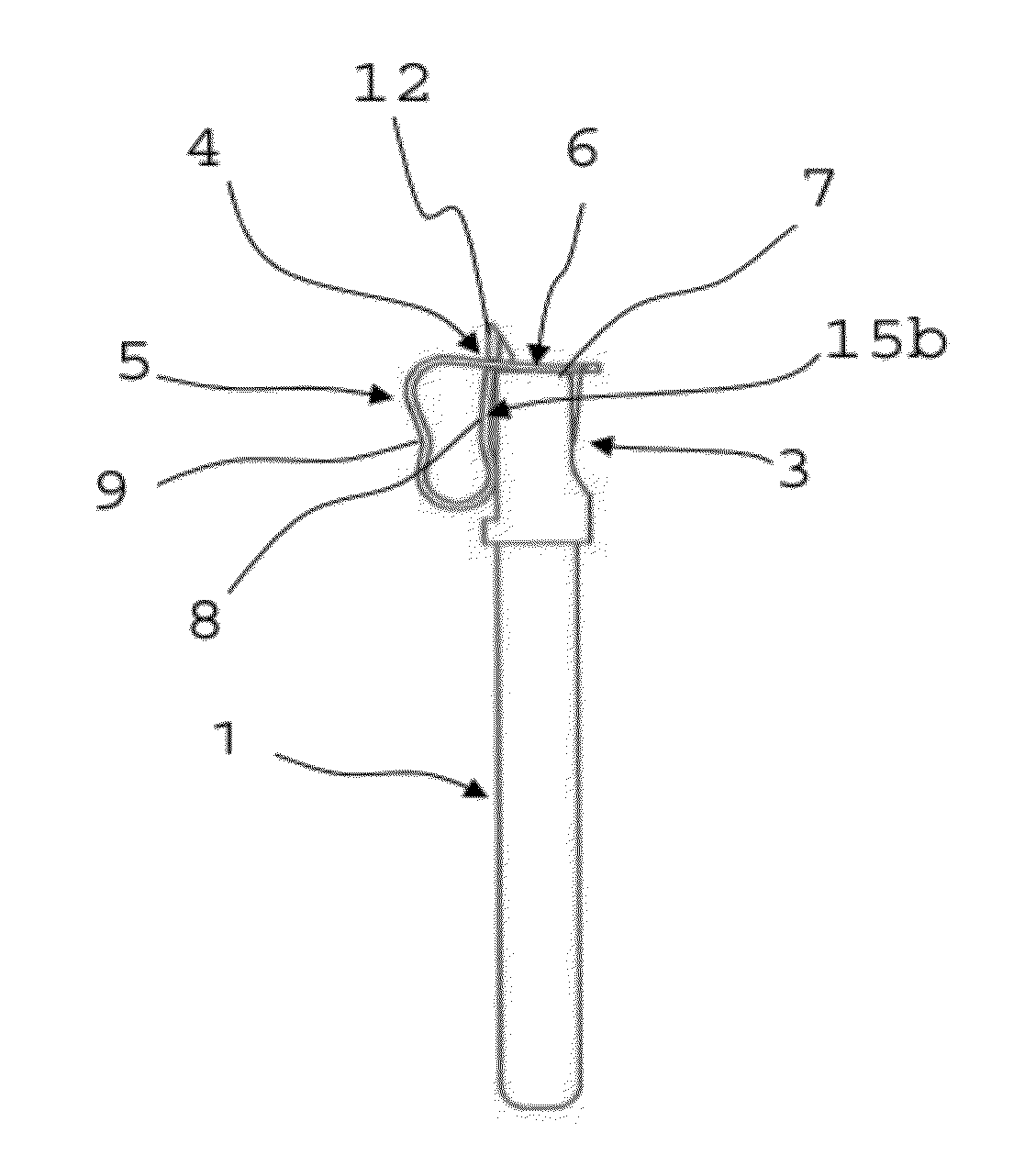
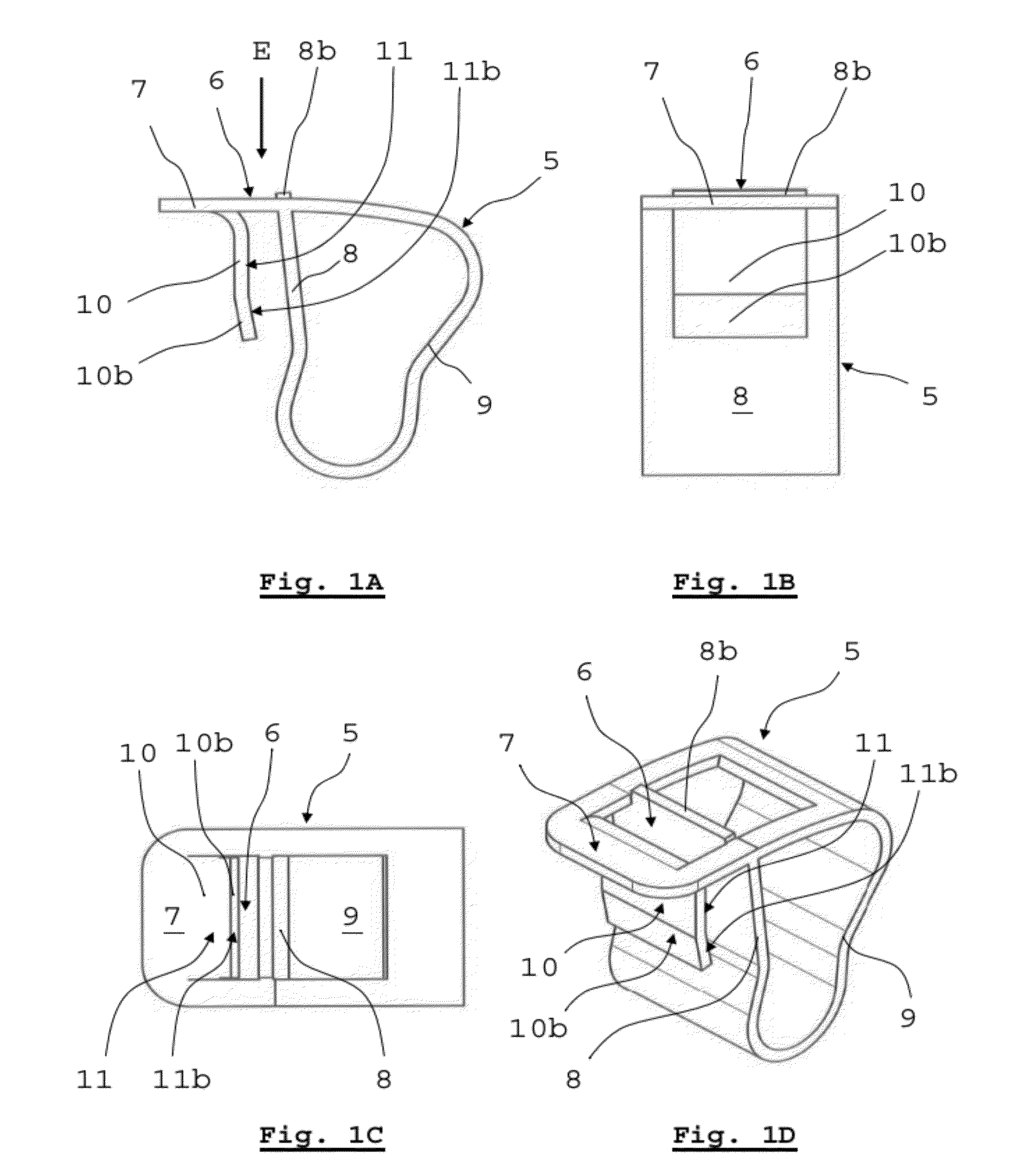
[0038]FIGS. 1A to 1D show an embodiment of a bent metal clamp spring 5 of the screwless connection terminal which has a clamping leg 7 and an abutting leg 8. Both spring legs 7, 8 are connected to each other via a tensioning leg 9 (FIG. 1A). In the clamping leg 7 of the clamp spring 5, a clamp opening 6 is recessed (FIG. 1C) which allows for a crossing of the clamping leg 7 and the abutting leg 8 by means of a segment 8b of the abutting leg 8 (FIG. 1D). The clamp opening 6 of the clamp spring 5 enables inserting the conductor cores 2b of the conductor 2 into the insertion device E. Relative to the clamping leg 7 of the clamp spring 5, the clamping leg 7 further has a conductor clamp extension 10 which is angled at an angle of substantially 90 degrees and which is aligned in the direction of the abutting leg 8 and the clamping face 11 of which is substantially oriented in a clamping plate-like manner parallel to the surface of the conductor clamp extension. Thus, the conductor clamp ...


PUM

PropertyMeasurementUnit
angleaaaaaaaaaa
electric currentsaaaaaaaaaa
rectangular shapeaaaaaaaaaa

Abstract

A screwless connection terminal with a contact element to which a conductor is to be electrically connected, the contact element comprising a connecting section and a contact surface, with a clamp spring by means of which the conductor is to be clamped to the contact surface of the contact element, wherein the clamp spring has a clamping leg, an abutting leg and a tensioning leg, wherein a clamp opening is formed in the clamping leg, through which clamp opening, the conductor is to be led, wherein the abutting leg of the clamp spring abuts on the contact element, and the tensioning leg of the clamp spring connects the abutting leg to the clamping leg, wherein the clamping leg further comprises a conductor clamp extension with a clamping face which is aligned substantially parallel to the contact surface of the contact element.

Description

CROSS-REFERENCE TO RELATED APPLICATIONS[0001]European patent application EP 10013544.1, filed Oct. 12, 2010, is incorporated herein by reference.FIELD OF THE INVENTION[0002]The invention relates to a screwless connection terminal for connecting an electrical conductor, in particular for an electrical plug connector device.BACKGROUND OF THE INVENTION[0003]As is well known, generic screwless connection terminals which usually have clamp springs, which often are designated as cage clamp springs, have the advantage that a conductor to be electrically connected can be mounted without screwing means. Through the principle of clamping the core ends of the conductor, which basically can be a single- or multi-core electric cable with a stranded wire line, a solid wire or a conductor inserted in a core end ferrule, to a contact element, an automatic adaptation to the respective cross-section takes place. This makes it possible that one and the same connection terminal can be used for differen...

Claims


Application Information

Patent Timeline
Patent Type & Authority Applications(United States)
IPC IPC(8): H01R4/48H01R43/00
CPCH01R4/4845Y10T29/49117H01R13/111H01R4/48455
Inventor RAMM, ANDREASSCHEPE, WALTER
Owner BALS ELEKTROTECHN
Why Eureka
Try Eureka