Brushless motor

Inactive Publication Date: 2012-04-19
ASMO CO LTD
View PDF8 Cites 32 Cited by
  • Summary
  • Abstract
  • Description
  • Claims
  • Application Information

AI Technical Summary

Benefits of technology

[0004]It is an object of the present invention to provide a brushless motor including a rotor with a consequ

Problems solved by technology

This may cause a torque decrease that low

Method used


Image

  • Brushless motor
  • Brushless motor
  • Brushless motor

Examples


Embodiment Construction

[0020]One embodiment of the present invention will now be described with reference to the drawings.

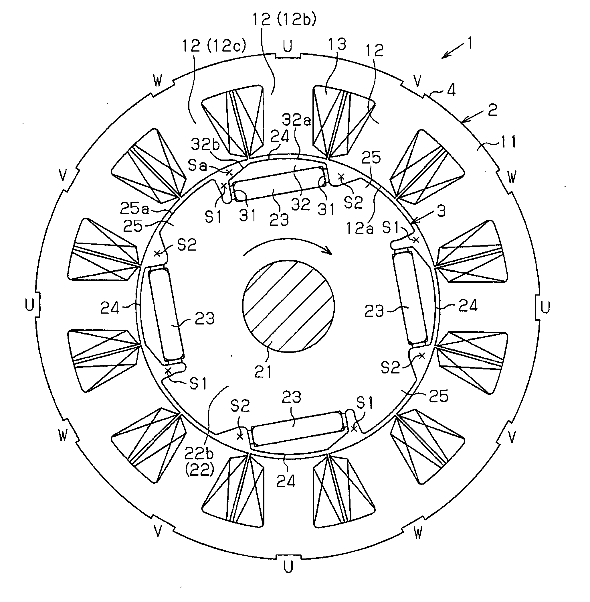
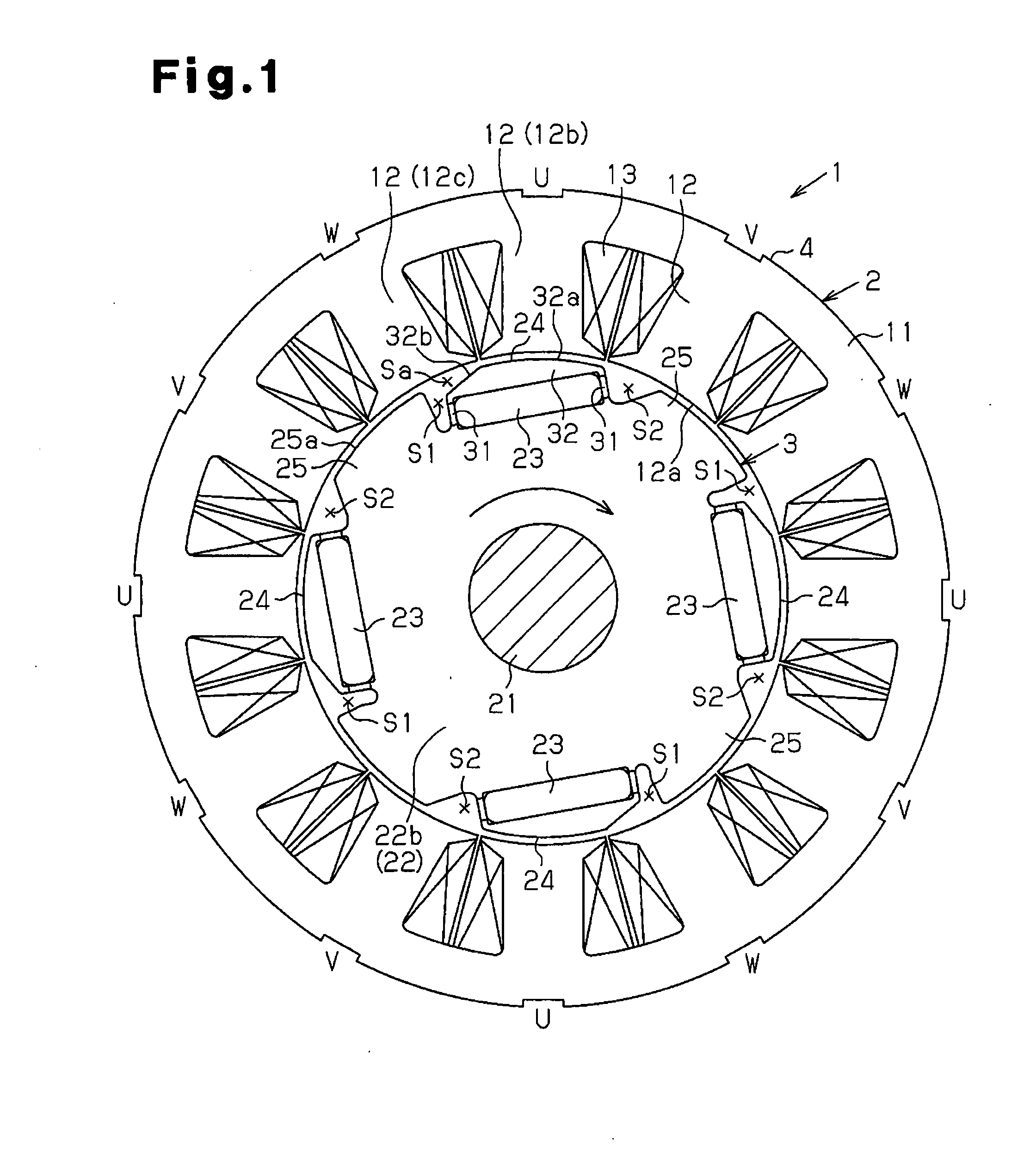
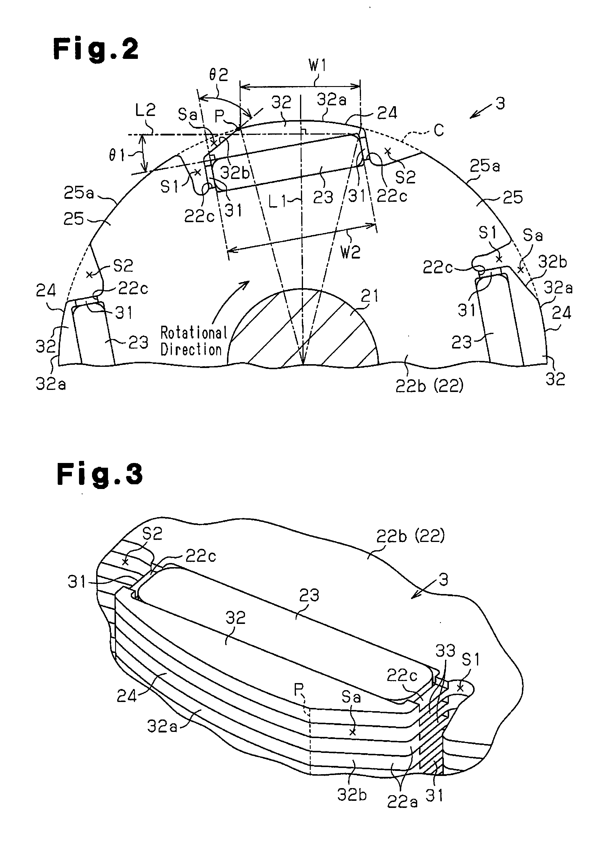
[0021]As shown in FIG. 1, an inner rotor type brushless motor 1 of the present embodiment includes an annular stator 2 and a rotor 3 arranged inward in the radial direction from the stator 2.

[0022]The stator 2 includes a stator core 4. The stator core 4 includes an annular part 11 and a plurality of (twelve in the present embodiment) teeth 12. The teeth 12 are arranged in the circumferential direction and extend inward in the radial direction from the annular part 11. The stator core 4 is formed by a stacking a plurality of core sheets in the axial direction. Each core sheet is formed by a metallic sheet having high permeability. A coil 13 is wound around each tooth 12 of the stator core 4 with an insulator (not shown) arranged in between. The coils 13 generate magnetic field, which rotates the rotor 3. Each coil 13 is wound around a predetermined one of the teeth 12 and forms one of t...


PUM


Abstract

A brushless motor includes a rotor and a stator. The rotor is provided with a rotor core including a plurality of magnet poles and a plurality of core poles. A void is formed at a boundary between each core pole and an adjacent magnet pole in the circumferential direction. Each magnet pole includes a peripheral core portion located closer to the stator than the magnet in the radial direction of the rotor. The void formed in at least one of two circumferential sides of each magnet pole includes an extended void region that extends into the peripheral core portion toward a middle point of the magnet pole in the circumferential direction.

Description

BACKGROUND OF THE INVENTION[0001]The present invention relates to a brushless motor including a rotor with a consequent-pole structure.[0002]A brushless motor includes a rotor and a stator (refer to, for example, Japanese Laid-Open Patent Publication No. 2004-201406). The rotor includes a rotor core. The rotor core includes a plurality of magnet poles (referred hereafter as the magnet poles) and a plurality of core magnet poles (hereafter referred to as the core poles). The magnet poles are arranged in the circumferential direction of the rotor core. Each of the core poles is arranged between two magnet poles that are adjacent to each other in the circumferential direction. A magnet is embedded in each magnet pole. A void is formed at a boundary between the core pole and the magnet pole that are adjacent to each other in the circumferential direction. The stator includes a plurality of teeth arranged at equal angular intervals in the circumferential direction. The teeth face the rot...

Claims


Application Information

Patent Timeline
IPC IPC(8): H02K21/12
CPCH02K1/276H02K2213/03H02K2201/03H02K29/03H02K1/2746
Inventor TAKEMOTO, YOSHIAKISANTO, SHINJIGOTO, KENTAKATO, SHIGEMASA
Owner ASMO CO LTD
Why Eureka
Try Eureka