Correction of counting errors in the evaluation of current ripples in a DC motor

a technology of dc motor and current ripple, which is applied in the direction of dc motor rotation control, motor/generator/converter stopper, dynamo-electric converter control, etc., can solve the problem of increasing the risk of error, unable to count the current ripple, and not being able to error-free count the current ripple of the motor

Inactive Publication Date: 2012-04-19
BROSE FAHRZEUGTEILE GMBH & CO KG HALLSTADT (DE)
View PDF2 Cites 12 Cited by
  • Summary
  • Abstract
  • Description
  • Claims
  • Application Information

AI Technical Summary

Benefits of technology

[0015]It is therefore an object of the invention to provide an easy-to-implement and failsafe method for determining an actuating quantity, in particular a travel position or travel speed of a commutator motor, by counting motor current ripples. The method should allow, in particular, an easy-to-implement and failsafe correction of errors in ripple counting. The invention has the additional object of specifying a device that is especially suitable for carrying out the method.

Problems solved by technology

However, error-free counting of the motor current ripples is not possible in all phases of a typical actuation process.
As a result of the collapsing motor current, it is impossible to count the current ripples in the freewheeling phase, in particular.
Ripple counting is indeed possible in principle during the startup and braking phases, but suffers an increased risk of error on account of comparatively irregular current relationships.
In conventional methods for ripple counting, this is why counting errors in ripple counting typically occur during the freewheeling phase in particular, but to a lesser degree in the startup phase and the braking phase as well.
Such counting errors occur primarily because current ripples in the current signal are not detected and thus are essentially “lost.” Furthermore, however, counting errors can also occur because externally caused disturbances in the motor current behavior are incorrectly identified as current ripples.
Both types of counting errors result in errors determining the actuating quantities.
Especially during calculation of the actuation position, these errors can accumulate in an unfavorable manner during the course of several successive actuation processes, and thus can significantly impair the function of the actuating device under certain circumstances.

Method used


Image

  • Correction of counting errors in the evaluation of current ripples in a DC motor
  • Correction of counting errors in the evaluation of current ripples in a DC motor
  • Correction of counting errors in the evaluation of current ripples in a DC motor

Examples


Embodiment Construction

[0043]Corresponding parts and quantities are labeled with the same reference characters in the figures.

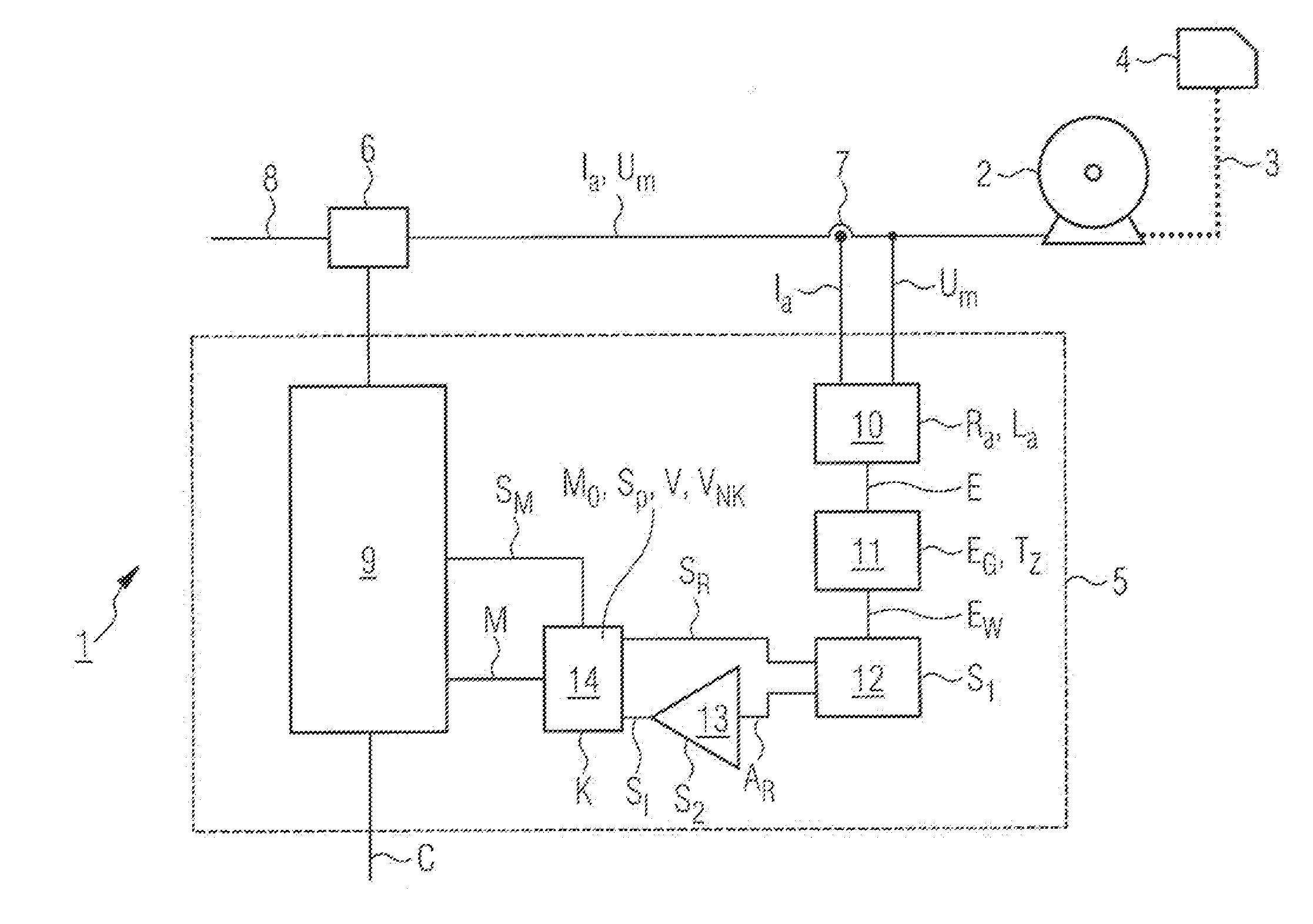
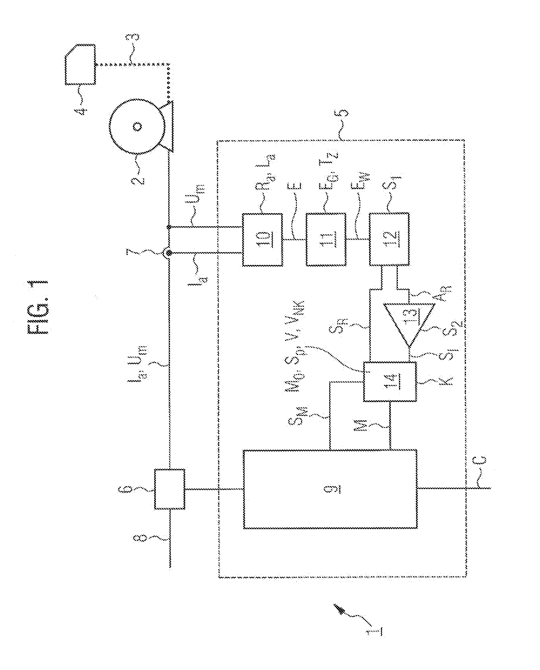
[0044]By way of example, the actuating device 1 shown schematically in FIG. 1 is an electric power window regulator, such as is customarily used in a passenger vehicle. The actuating device 1 includes a mechanically commutated (DC) motor 2, which acts, on a (motor vehicle) window 4 by means of an actuating mechanism 3 (merely indicated) and reversibly moves said window between an open position and a closed position.

[0045]The actuating device 1 also includes a control unit 5, a motor switch 6, and a current sensor 7.

[0046]The current switch 6 is connected in a (two-phase) power supply line 8 for the motor 2. It includes two independently drivable individual switches, the switching positions of which can be used to selectably connect the two motor terminals to the positive pole or the negative pole (ground) of the power supply line 8. By appropriately setting the individual switches ...


PUM


Abstract

A method for detecting a regulating variable of a mechanically commutated DC motor in a positioning device for a motor vehicle is provided. The DC motor has a standard ripple pattern, which contains per engine cycle or semi-cycle at least one index ripple, which is classified with regard to amplitude, duration and / or time position. The counter-electromotoric power is calculated from a measured motor current and the measured motor voltage by a motor model. An alternating element corresponding to the current ripples is extracted from the counter-electromotoric power, which in turn is used to determine the current ripples. Further, in at least one engine cycle or engine semi-cycle the index ripple is identified and the total identified current ripples are counted. The result of the count is hereby corrected when the index ripple is not counted at the expected position.

Description

[0001]This nonprovisional application is a continuation of International Application No. PCT / EP2010 / 001635, which was filed on Mar. 16, 2010, and which claims priority to German Patent Application No. DE 10 2009 013 062.4, which was filed in Germany on Mar. 16, 2009, and which are both herein incorporated by reference.BACKGROUND OF THE INVENTION[0002]1. Field of the Invention[0003]The invention relates to a method for determining an actuating quantity of a mechanically commutated DC motor (commutator motor). The invention additionally relates to a device for carrying out the method, and to the use of a modified commutator motor for such a method.[0004]2. Description of the Background Art[0005]Commutator motors are oftentimes used as actuating motors within an actuating device for or in a motor vehicle. Such actuating devices are, for example, an electric power window regulator, an electric seat adjustment mechanism, an electric door or sunroof closing mechanism.[0006]In these actuat...

Claims


Application Information

Patent Timeline
Patent Type & Authority Applications(United States)
IPC IPC(8): H02P7/00
CPCH02K23/30H02K23/66H02P7/0094H02P7/0038H02P7/00H02P7/03H02P7/02
Inventor KNEZEVIC, JOVANUEBEL, WOLFGANG
Owner BROSE FAHRZEUGTEILE GMBH & CO KG HALLSTADT (DE)
Why Eureka
Try Eureka