Electrically Conductive Kelvin Contacts For Microcircuit Tester

a microcircuit tester and electrical conductor technology, applied in electrical testing, measurement devices, instruments, etc., can solve the problems of reducing the value of the circuit board at that point, affecting the test results, so as to achieve the effect of limiting the possibility of flexur

Active Publication Date: 2012-04-19
JOHNSTECH INT
View PDF2 Cites 16 Cited by
  • Summary
  • Abstract
  • Description
  • Claims
  • Application Information

AI Technical Summary

Benefits of technology

[0049]An embodiment is a device for forming a plurality of temporary mechanical and electrical connections between a device under test having a plurality of terminals and a load board having a plurality of contact pads, each contact pad being laterally arranged to correspond to exactly one terminal, comprising: a laterally oriented, electrically insulating housing longitudinally adjacent to the contact pads on the load board; a plurality of electrically conductive force contacts extending through longitudinal holes in the housing toward the device under test and being compressible/deflectable through the holes in the housing, each force contact in the plurality being laterally arranged to correspond to exactly one terminal; and a plurality of electrically conductive sense contacts, each sense contact in the plurality being lateral

Problems solved by technology

As microcircuits continually evolve to be smaller and more complex, the test equipment that tests the microcircuits also evolves.
Mounting a defective microcircuit on a circuit board is relatively costly.
Once mounted on a circuit board, removing a microcircuit is problematic because the very act of melting the solder for a second time ruins the circuit board.
Thus, if the microcircuit is defective, the circuit board itself is probably ruined as well, meaning that the entire value added to the circuit board at that point is lost.
Each microcircuit must be tested in a way that identifies all defective devices, but yet does not improperly identify good devices as defective.
Either kind of error, if frequent, adds substantial overall cost to the circuit board manufacturing process, and can add retest costs for devices improperly identified as defective devices.
Microcircuit test equipment itself is quite complex.
Because of the small size of microcircuit contacts and the spacings between them, even small errors in making the contact will result in incorrect connections.
Connections to the microcircuit that are misaligned or otherwise incorrect will cause the test equipment to identify the device under test (DUT) as defective, even though the reason for the failure is the defective electrical connection between the test equipment and the DUT rather than defects in the DUT itself.
A further problem in microcircuit test equipment arises in automated testing.
The sheer number of tests cause wear on the tester contacts making electrical connections to the microcircuit terminals during testing.
This wear dislodges conductive debris from both the tester contacts and the DUT terminals that co

Method used


Image

  • Electrically Conductive Kelvin Contacts For Microcircuit Tester
  • Electrically Conductive Kelvin Contacts For Microcircuit Tester
  • Electrically Conductive Kelvin Contacts For Microcircuit Tester

Examples


Embodiment Construction

[0095]A general summary of the disclosure follows.

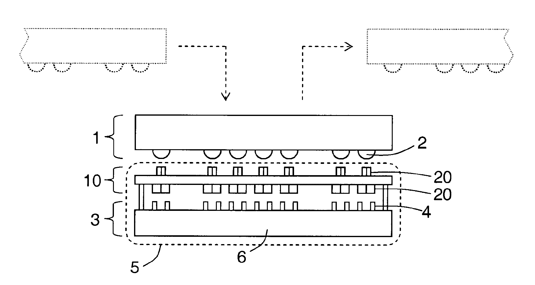
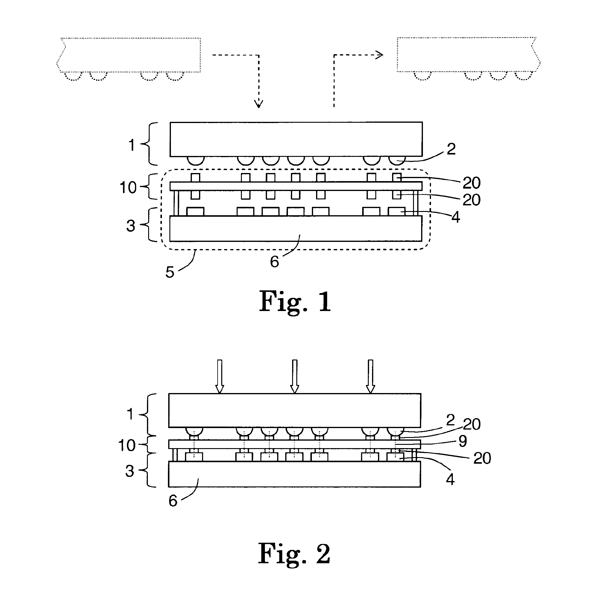
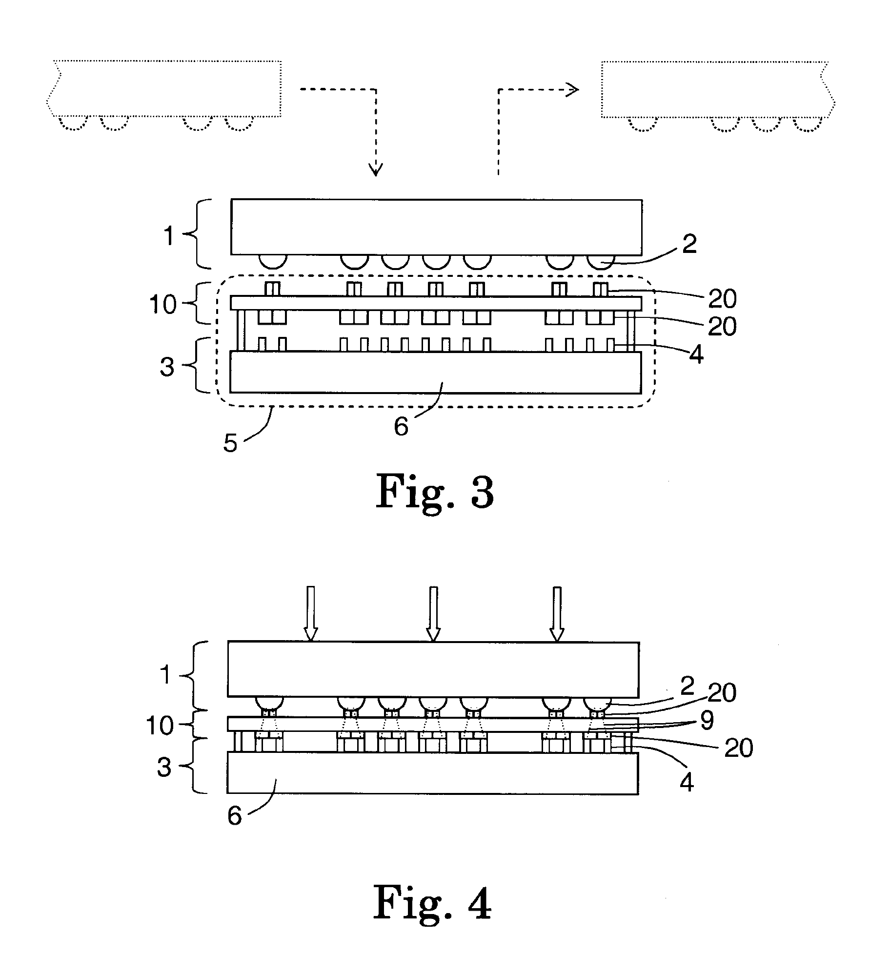
[0096]The terminals of a device under test are temporarily electrically connected to corresponding contact pads on a load board by a series of electrically conductive contacts. The terminals may be pads, balls, wires (leads) or other contact points. Each terminal that undergoes Kelvin testing connects with both a “force” contact and a “sense” contact, with each contact electrically connecting to a respective, single contact pad on the load board. The force contact delivers a known amount of current to or from the terminal, and the sense contact measures a voltage at the terminal and draws a negligible amount of current to or from the terminal. The sense contact partially or completely laterally surrounds the force contact, so that it need not have its own resiliency, though it may also be resilient in its own right. This helps keep the force contact in alignment by preventing lateral wobbling. In a first case, the sense contact has a...


PUM


Abstract

Terminals (2, 502) of a device under test (DUT) are connected to corresponding contact pads or leads by a series of electrically conductive contacts. Each terminal testing connects with both a “force” contact and a “sense” contact. In one embodiment, the sense contact (770) partially or completely laterally surrounds the force contact (700). In order to increase the contact surface, the force contact, in a spring pin (700) configuration contacts the device under test terminal at that portion of the lead which is curved or angled, rather than orthogonal to the pin.

Description

CROSS-REFERENCE TO RELATED APPLICATIONS[0001]This application is a continuation in part (CIP) of U.S. Ser. No. 12 / 764,603 filed 21 Apr. 2010 and further claims priority of U.S. provisional application No. 61 / 171,141, filed on 21 Apr. 2009, provisional application No. 61 / 257,236, filed on 2 Nov. 2009, and provisional application No. 61 / 307,501, filed on 24 Feb. 2010, which hereby is incorporated herein by reference in its entirety.BACKGROUND[0002]1. Field[0003]The present disclosure is directed to equipment for testing microcircuits.[0004]2. Description of the Related Art[0005]As microcircuits continually evolve to be smaller and more complex, the test equipment that tests the microcircuits also evolves. There is an ongoing effort to improve microcircuit test equipment, with improvements leading to an increase in reliability, an increase in throughput, and / or a decrease in expense.[0006]Mounting a defective microcircuit on a circuit board is relatively costly. Installation usually in...

Claims


Application Information

Patent Timeline
IPC IPC(8): G01R1/067
CPCG01R1/0466
Inventor ERDMAN, JOEL N.SHERRY, JEFFREY C.MICHALKO, GARY W.
Owner JOHNSTECH INT
Why Eureka
Try Eureka