Antenna and antenna module

a technology which is applied in the field of antenna module and antenna, can solve the problems of inconvenient data communication configuration, weak magnetic field which can be radiated from the antenna, and small communication distance, so as to improve the level of communication signal, facilitate data communication, and facilitate data communication

Inactive Publication Date: 2012-04-19
MURATA MFG CO LTD
View PDF5 Cites 84 Cited by
  • Summary
  • Abstract
  • Description
  • Claims
  • Application Information

AI Technical Summary

Benefits of technology

[0039]With this configuration, the antenna having the configuration described above is used as a resonant antenna, and the magnetic field radiated from the base antenna is significantly amplified. Accordingly, the level of a communication signal is greatly improved when compared with a case where only the base antenna is used, and a lar...

Problems solved by technology

Therefore, a magnetic field which can be radiated from the antenna becomes weak and a communication-available distance becomes small.
Accordingly,...

Method used


Image

  • Antenna and antenna module
  • Antenna and antenna module
  • Antenna and antenna module

Examples


Embodiment Construction

[0059]An antenna according to a first preferred embodiment of the present invention will be described with reference to the accompanying drawings.

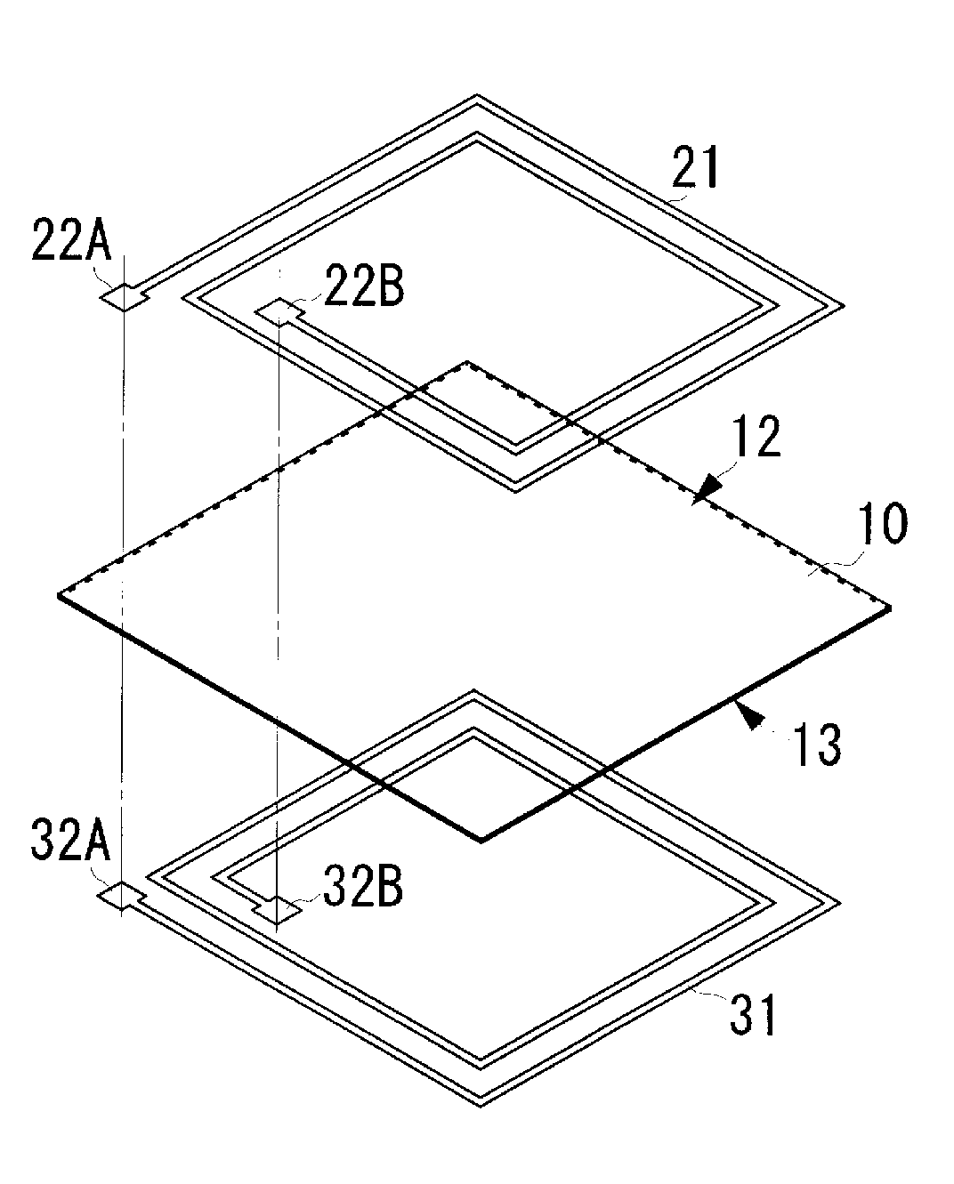
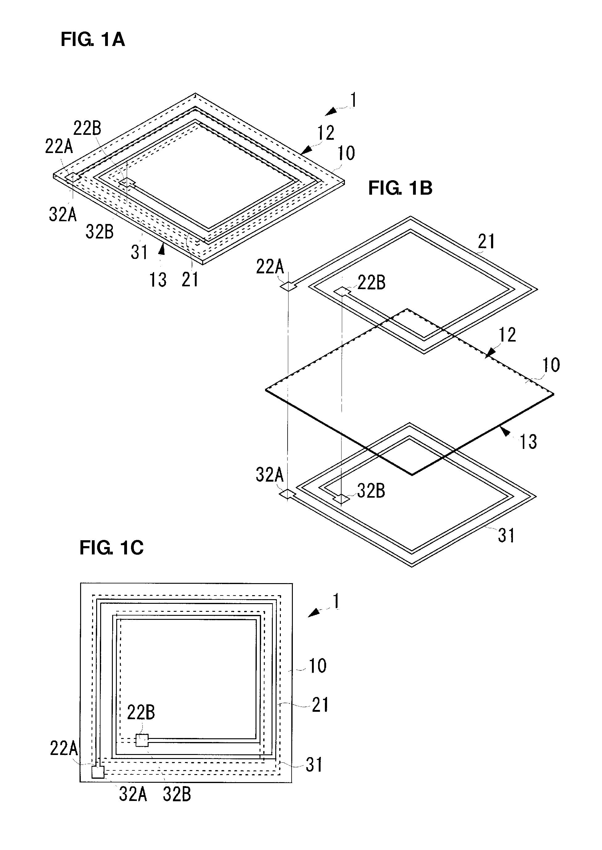
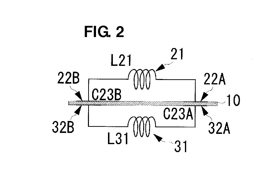
[0060]FIGS. 1A-1C include diagrams illustrating a configuration of an antenna 1 according to the first preferred embodiment. Specifically, FIG. 1A is a perspective view, FIG. 1B is an exploded perspective view, and FIG. 1C is a plan view illustrating the antenna 1 viewed from a first main surface 12 side. FIG. 2 is a diagram illustrating an equivalent circuit of the antenna 1 shown in FIGS. 1A-1C viewed from a side thereof.

[0061]The antenna 1 includes a flexible sheet 10 which is a flat thin film formed of insulation material such as resin. The flexible sheet 10 includes the first main surface 12 including a first coil electrode 21 located thereon and a second main surface 13 which faces the first main surface 12 and which includes a second coil electrode 31 located thereon. The first and second coil electrodes 21 and 31 preferably are lin...


PUM


Abstract

An antenna includes a flexible sheet that includes a first main surface including a first coil electrode located thereon and a second main surface including a second coil electrode located thereon. The first and second coil electrodes are wound in opposite directions when viewed from different directions. A first end of the first coil electrode faces a first end of the second coil electrode through the flexible sheet. Similarly, a second end of the first coil electrode faces a second end of the second coil electrode through the flexible sheet. The first and second coil electrodes define an inductor, the first ends of the first and second coil electrodes define a capacitor, and the second ends of the first and second coil electrodes define a capacitor whereby a resonant antenna is provided.

Description

BACKGROUND OF THE INVENTION[0001]1. Field of the Invention[0002]The present invention relates to an antenna and an antenna module used for communication utilizing electromagnetic coupling such as RFID communication.[0003]2. Description of the Related Art[0004]In recent years, proximity communication systems using various non-contact ICs have been broadly used in various fields. Such a communication system includes a non-contact IC card including a wireless communication IC and a card reader. In this communication system, when the non-contact IC card is moved closer to the card reader within a predetermined distance, communication is performed. To perform the communication, an antenna in which a resonant frequency is set in accordance with a frequency of a communication signal is required. Such an antenna disclosed in Japanese Unexamined Patent Application Publication No. 2001-84463 and Japanese Unexamined Patent Application Publication No. 10-334203 basically has a coil electrode wo...

Claims


Application Information

Patent Timeline
IPC IPC(8): H01Q11/12
CPCG08B13/00H01Q21/0025H01Q7/00
Inventor KATO, NOBORUTANIGUCHI, KATSUMIIKEMOTO, NOBUOMURAYAMA, HIROMI
Owner MURATA MFG CO LTD
Why Eureka
Try Eureka