Mapping concentrations of airborne matter

a technology of airborne matter and concentration, applied in the field of methods, can solve the problems of inability to determine the variation of airborne matter concentration near a diffuse source, inability to use tracer techniques, and limited placement,

Active Publication Date: 2012-04-19
GOLDER ASSOCIATES
View PDF0 Cites 42 Cited by
  • Summary
  • Abstract
  • Description
  • Claims
  • Application Information

AI Technical Summary

Benefits of technology

[0030]The methods described herein allow for obtaining the concentration of airborne matter at a plurality of identified locations within a reasonable time frame and can be used to obtain such concentrations throughout the entire thickness and width of the emission plume and provide a two-dimensional or three-dimensional map of the concentration of airborne matter. The methods can account for variations of wind speed at various heights above the ground and may be applied to emission sources over a large area or height that may extend beyond an above-ground platform or into areas inaccessible, or poorly accessible by ground. The method employs existing airborne matter concentration measurement apparatus for rapidly mapping airborne matter concentrations in the air, and combines this mapping with wind velocity for measuring the emission discharge rate from an emission source. Complex numerical modeling of airborne matter dispersion, or release of a tracer gas is not required.
[0031]Methods according to various embodiments of the present invention may be useful for identifying the boundaries, or geographical locations within or surrounding the emission plume where the airborne matter concentration is at or below a selected concentration or flux value. For example, at a landfill site, it may be of interest to determine the location within the measurement surface where the airborne matter concentration is highest. By successive measurement surfaces across the landfill, the emission discharge rate from and location of high emission zones can be identified for increased landfill gas collection.

Problems solved by technology

Such an arrangement may involve the placement (permanently or temporarily) of a plurality of sensors or sampling devices; this placement may be limited by access to the site.
Estimates and extrapolations, while useful for monitoring and modeling emission plume movement, may not be suitable in some situations where defined values are desired.
However, tracer techniques cannot be used to determine the variation of airborne matter concentration near a diffuse source, and the tracer release pattern should mimic the emission flux pattern from the emission source.
However, it does not teach how to determine the concentration distribution of airborne matter within the plume or account for a natural background concentration of a pollutant in the atmosphere.
The airspace to be mapped is limited by the height of the mast and the area covered by the samplers, and may not be practical for large emission plumes spanning several hectares and / or of significant height.
In addition, the accuracy of the method for some gases is questionable due to the long absorption distance through the atmosphere.
In an emission flux measurement application, this equipment is ground based, expensive, heavy and bulky.
The DIAL instrument described does not map the concentration of airborne matter in the air, and there is no teaching of measuring or quantifying emission flux of the gas leak.

Method used


Image

  • Mapping concentrations of airborne matter
  • Mapping concentrations of airborne matter
  • Mapping concentrations of airborne matter

Examples


Embodiment Construction

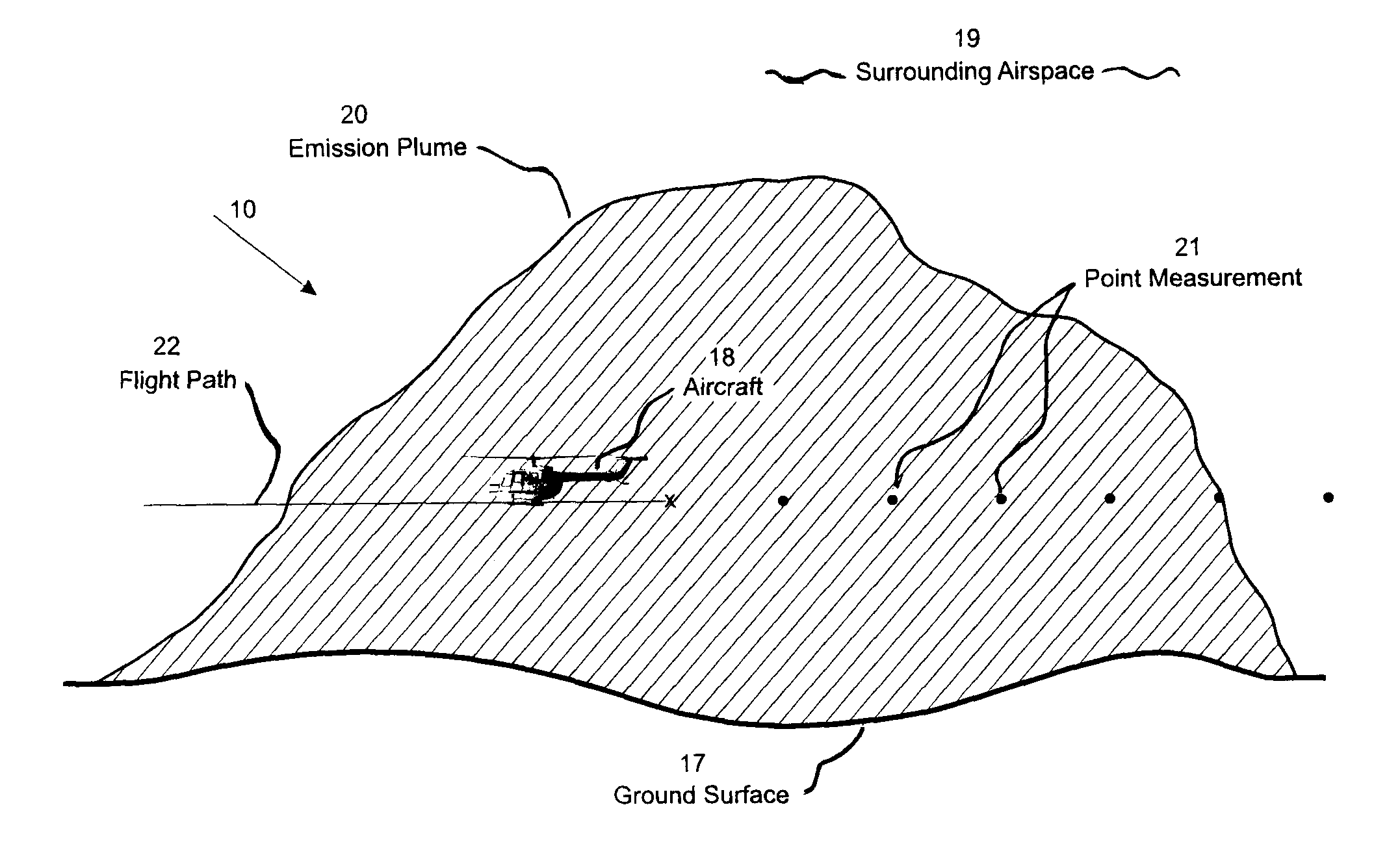
[0043]The present invention relates to a method of mapping concentrations of airborne matter in an emission plume using point sampling.

[0044]The following description is of a preferred embodiment.

[0045]The present invention provides a point measurement method of mapping airborne concentrations of airborne matter in an emission plume using point sampling. The method involves measuring airborne matter at one or more than one identified locations using an optical sensing instrument (OSI) mounted on a vehicle operatively connected with one or more than one matter samplers mounted on the vehicle. The one or more matter samplers are passed along one or more measurement paths through an airspace to be sampled, and one or more concentration measurements are obtained. A geographic position and an altitude value is established for each of the one or more identified locations, and a concentration measurement for the airborne matter for each identified location is then determined. The concentra...


PUM

PropertyMeasurementUnit
timeaaaaaaaaaa
speedaaaaaaaaaa
heightaaaaaaaaaa

Abstract

A method of mapping concentrations of airborne matter from an emission source of interest in an emission plume is provided. The method involves measuring airborne matter at one or more than one identified locations using an optical sensing instrument (OSI) operatively connected with one or more than one matter samplers and mounted on a vehicle. The one or more than one airborne matter samplers are passed through an airspace to be sampled, and one or more concentration measurements are obtained. Geographic positions and altitude values for each of the one or more identified locations are established, and a point concentration measurement for the airborne matter for each identified location determined. The concentration measurements are mapped relative to the geographic position and altitude values for each of the one or more identified locations to obtain an airborne matter concentration distribution map in one or more measurement surfaces through a cross-section or profile of the emission plume. The method further comprises a step of determining a representative wind velocity distribution at one or more measurement surfaces and calculating the mass flow rate of airborne matter across the measurement surface in mass per unit time.

Description

FIELD OF INVENTION[0001]The present invention relates to methods for mapping airborne concentrations of airborne matter in an emission plume.BACKGROUND OF THE INVENTION[0002]Fugitive emissions result from releases of airborne matter to the atmosphere from diffuse sources, which can include landfills, reservoirs, effluent ponds, mines, natural deposits, or even a collection of point-sources such as cities, industrial plants, or a herd of animals. Fugitive emissions can also include emissions from point sources, such as smokestacks, flares, wells, exhaust tubes, leaks and vent pipes, that have been released to the atmosphere. The airborne matters can be greenhouse gases, gaseous organic compounds, polluting gases, or particulate matter. The atmospheric volume within which the airborne matters exist is referred to as a plume. The flux is the mass flow rate per unit area. The mass flow rate is the flow rate of the airborne matter through an imaginary surface, for example downwind of an ...

Claims


Application Information

Patent Timeline
Patent Type & Authority Applications(United States)
IPC IPC(8): G01N21/84
CPCG01N2021/1793G01W1/00G01S17/95Y02A90/10
Inventor WONG, COLIN IRVIN
Owner GOLDER ASSOCIATES
Why Eureka
Try Eureka