Surface Light Source Assembly

a technology of surface light source and assembly, which is applied in the direction of lighting and heating apparatus, lighting support devices, instruments, etc., can solve the problems of affecting the construction efficiency the elasticity of the light guide plate made of synthetic resin, etc., to achieve the effect of simple construction

Inactive Publication Date: 2012-04-19
MEITAKU IND
View PDF15 Cites 23 Cited by
  • Summary
  • Abstract
  • Description
  • Claims
  • Application Information

AI Technical Summary

Benefits of technology

[0009]According to the present invention, the light guide plate is used as a base plate on which various elements or members of the surface light source assembly are overlapped. Namely, the reflective plate is overlapped on the rear surface of the light guide plate, and the screw movable hole for absorbing the heat expansion and contraction is arranged in the vertical plate of the supporting frame. Further, the reflective plate is fixed to the light guide plate by screwing the screw or bolt into the light guide plate via the screw movable hole. Thus, the surface light source assembly of the present invention is thin and simple in construction. Further, the surface light source assembly of the present invention can be applied to various types of surface light source equipments, such as, a display, a signboard or the like and maintaining the heat expansion and contraction functions of the light guide plate. The assembly of the present invention is thinner than the conventional surface light source assembly.
[0010]According to the present invention, the light diffuser plate or sheet which diffuse outgoing light from the light guide plate is arranged so as to prevent a light guiding pattern of the light guide plate from viewing from the front surface of the surface light source assembly and give rise to uniform emission from the surface light source assembly. The light guide plate and the reflective plate or sheet are fixed by screwing the screw or bolt into the light guide plate from the vertical plate of the supporting frame toward the insert-nut arranged in the light guide plate. Thus the light guide plate and the reflective plate or sheet can be securely and firmly fixed accommodating the heat expansion and contraction of the light guide plate. In addition, the transparent cover is overlapped on the top surface of the light guide plate. Further, the end holding frame is arranged at upper and lower and right and left edges of the surface light source assembly crossing with the supporting frame so as to hold the transparent cover, which permits installation or change of light transparent medium such as a positive film easily perform by removing the transparent cover. Although the end holding frame is used in the surface light source assembly, the effective lighting surface of the light source assembly can be wide without narrowing the light surface of the light source by the end holding frame.

Problems solved by technology

Furthermore, when the surface light source assembly is located at a high-temperature place or a high-humidity place, the light guide plate made of the synthetic resin is liable to expand and contract.
More specifically, for example, when the surface light source assembly is located at a place where the light guide plate is exposed outdoors facing the south and receiving the direct sun light, the light guide plate made of synthetic resin is liable to expand by the heat.

Method used


Image

  • Surface Light Source Assembly
  • Surface Light Source Assembly
  • Surface Light Source Assembly

Examples


Embodiment Construction

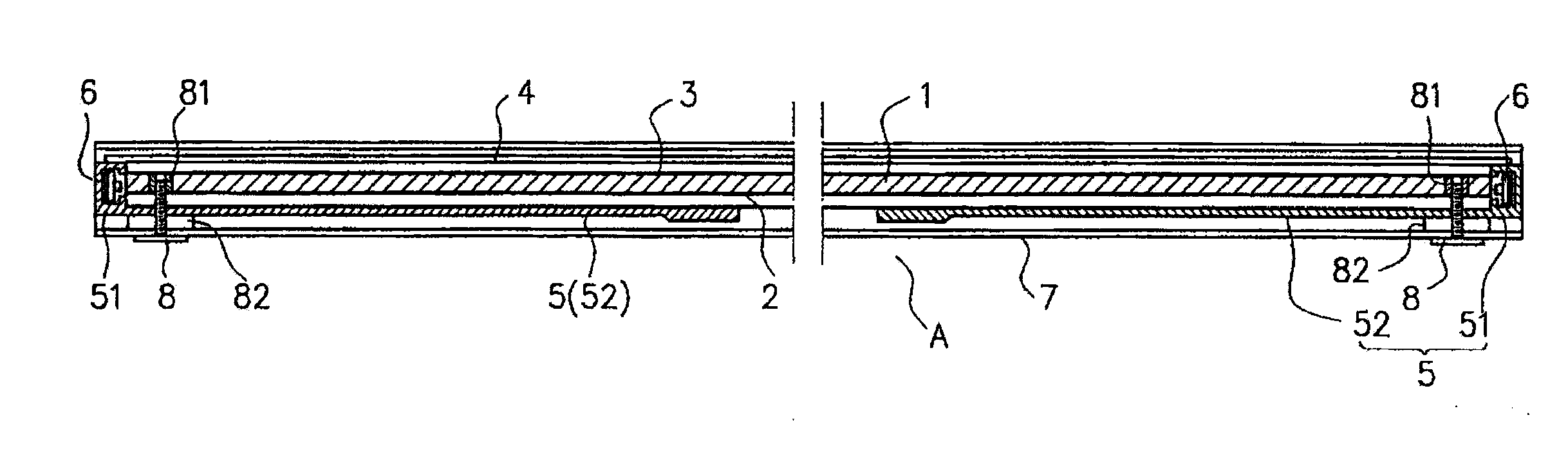
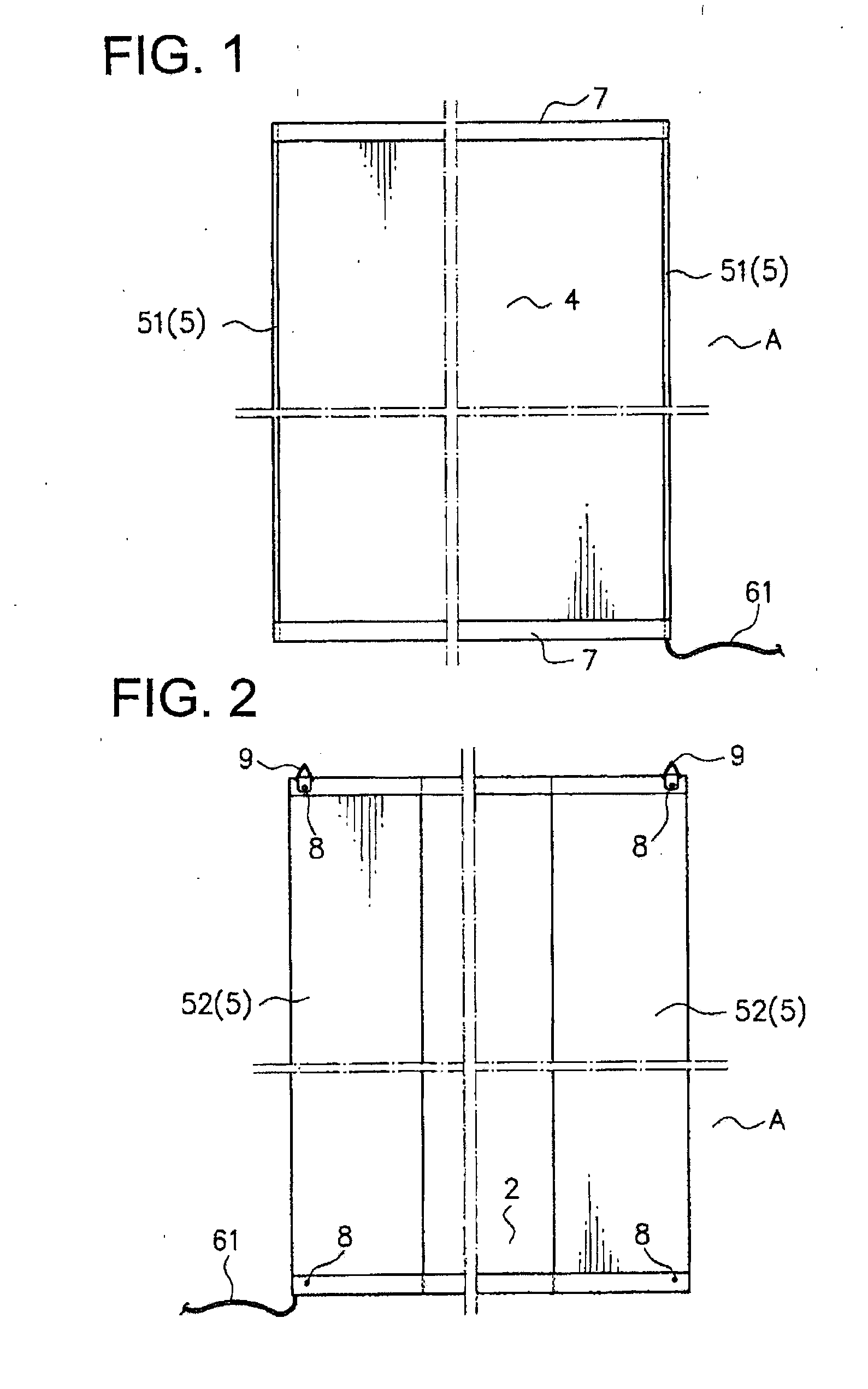
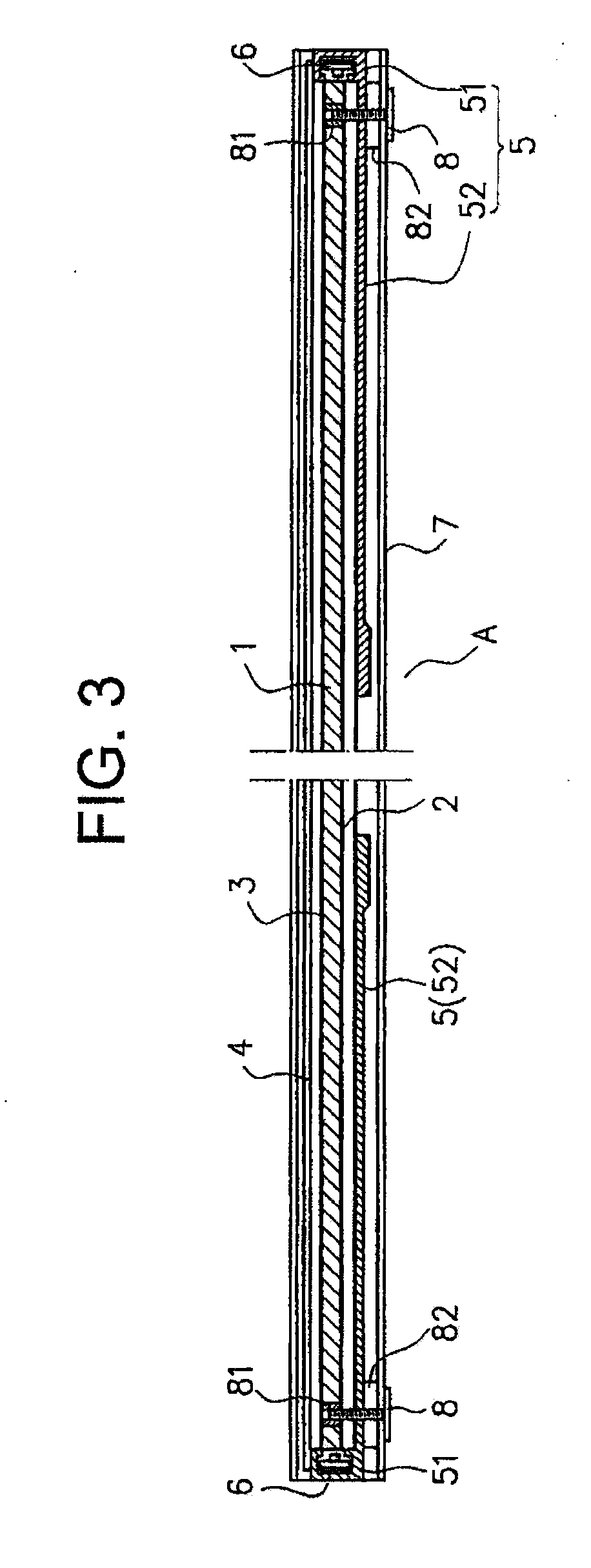
[0018]A surface light source assembly according to an embodiment of the present invention will be explained with reference to the drawings. The surface light source assembly A absorbs a heat expansion and contraction of a light guide plate 1 made of synthetic resin by a screw or bolt 8 screwed into the light guide plate 1 through a screw movable hole 53 of the light guide plate 1. The screw movable hole 53 is arranged on a supporting frame 5 to absorb the heat expansion and contraction of the light guide plate 1 made of the synthetic resin resulted from LED light sources used in the surface light source assembly effectively and properly. For example, the heat expansion and contraction of the light guide plate 1 generated in a place where it is subjected to the temperature of 70° or more by the LED light source or a high temperature inside of a house facing the south or outside of a house where it is subjected to direct sunlight is effectively and properly absorbed. The generation of...


PUM


Abstract

A surface light source assembly is disclosed. The surface light source assembly includes a light guide plate, a reflective sheet, a light diffuser sheet and a transparent cover arranged in front of the light diffuser sheet, an insert-nut embedded in the light guide plate, and a supporting frame having a vertical plate and a screw movable hole arranged on the vertical plate. In the insert-nut, a screw is screwed from an end holding frame overlapped on both ends of the supporting frame and arranged in both ends of the light guide plate via the screw movable hole. The screw can be moved in the screw movable hole depending on a heat expansion and contraction of the light guide plate.

Description

CROSS REFERENCE TO RELATED APPLICATION[0001]This application claims priority of Japan Patent Application No. 2011-174683 and the fuel content of that application is incorporated by reference.TECHNICAL FIELD[0002]The present invention relates to a lighting equipment in which a incident light of LED light source is illuminated by a light guide plate, and more particularly to a surface light source assembly used for a display or a signboard in which a light transmission medium such as a positive film arranged between the light guide plate and a transparent cover is illuminated from backward by the incident light from the LED light source via the light guide plate.BACKGROUND OF THE INVENTION[0003]In this type of the surface light source assembly, the light guide plate made of synthetic resin may expand or contract due to heat from the LED light source when the large LED light source is used so as to illuminate with high brightness. Furthermore, when the surface light source assembly is ...

Claims


Application Information

Patent Timeline
Patent Type & Authority Applications(United States)
IPC IPC(8): F21V21/00F21V7/00F21V8/00
CPCG02B6/0093F21Y2105/00G02B6/0051G02B6/0091F21V17/12G02B6/0001
Inventor MATSUI, HIROKAZU
Owner MEITAKU IND
Why Eureka
Try Eureka