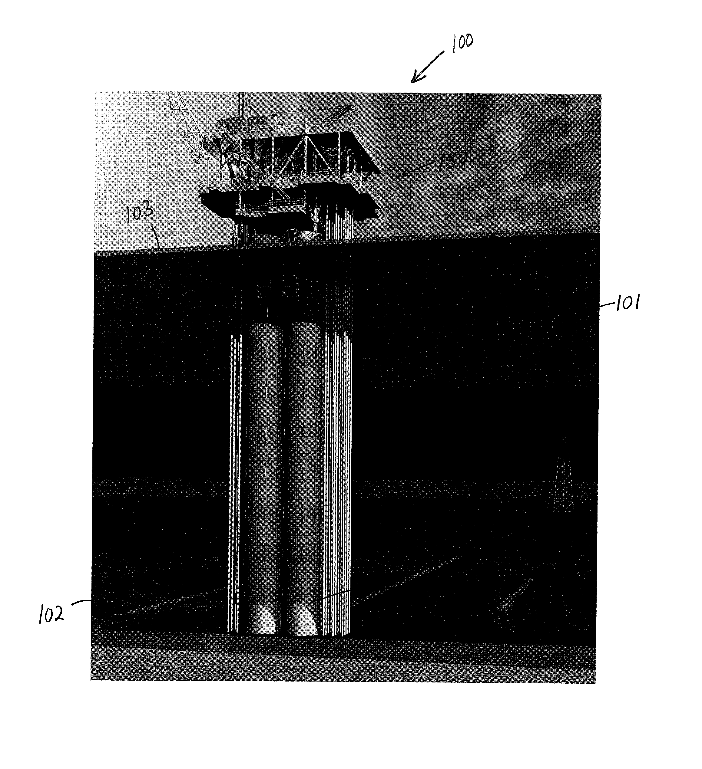
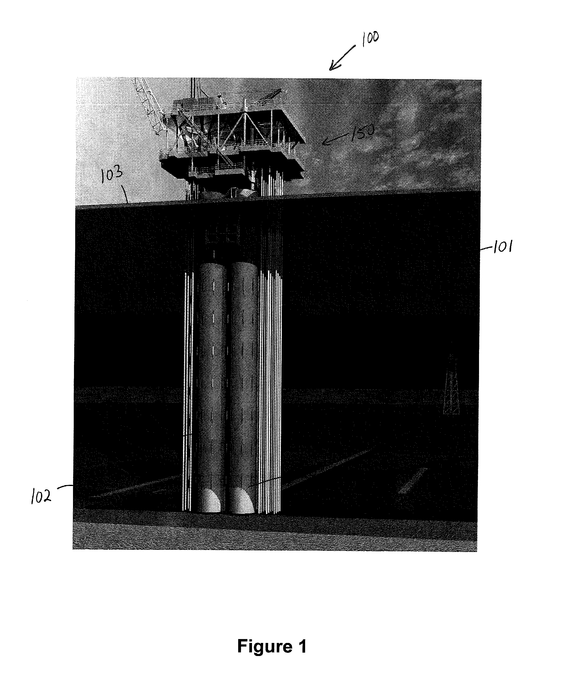
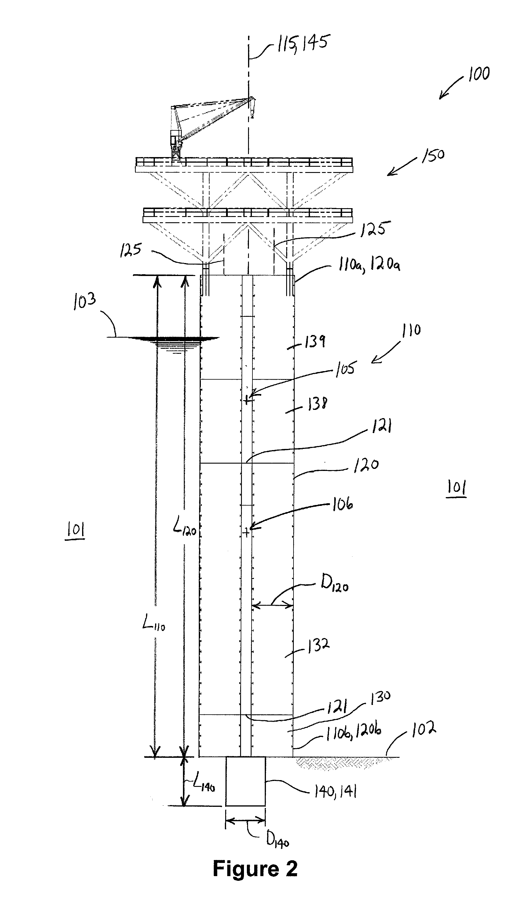
Offshore tower for drilling and/or production

a technology for offshore towers and production, applied in special-purpose vessels, vessel construction, transportation and packaging, etc., can solve the problems of increasing the infrastructure and labor requirements for fabrication and installation of jackets, affecting the efficiency of construction, and affecting the efficiency of installation and maintenance of fixed jacket platforms

Active Publication Date: 2012-04-19
WISON OFFSHORE TECH INC
View PDF25 Cites 16 Cited by
  • Summary
  • Abstract
  • Description
  • Claims
  • Application Information

AI Technical Summary

Benefits of technology

[0014]Embodiments described herein comprise a combination of features and advantages intended to address various shortcomings associated with certain prior devices, systems, and methods. The various characteristics described above, as well as other features, will be readily apparent to those skilled in the art upon reading the following detailed description, and by referring to the accompanying drawings.

Problems solved by technology

In addition, installation of a fixed platform often requires the installation of piles that are driven into the seabed to anchor the jacket thereto.
In other regions, having little to no experience with fixed jacket platforms, the facilities, equipment, infrastructure, and labor may be insufficient to efficiently construct, deploy, and install a fixed jacket platform.
Moreover, even in some regions, such as Brazil and Peru, that have some experience fabricating and installing fixed jacket platforms, the range of applications for fixed jacket platforms anticipated in the next few years may exceed present capabilities.
Such changes may further increase the infrastructure and labor requirements for fabrication and installation of the jacket.
However, the lower end of the truss structure is typically secured to the sea floor with piles that are driven into the sea bed, and thus, provides some of the same installation challenges as fixed jacket platforms.

Method used


Image

  • Offshore tower for drilling and/or production
  • Offshore tower for drilling and/or production
  • Offshore tower for drilling and/or production

Examples


Embodiment Construction

[0024]The following discussion is directed to various exemplary embodiments. However, one skilled in the art will understand that the examples disclosed herein have broad application, and that the discussion of any embodiment is meant only to be exemplary of that embodiment, and not intended to suggest that the scope of the disclosure, including the claims, is limited to that embodiment.

[0025]Certain terms are used throughout the following description and claims to refer to particular features or components. As one skilled in the art will appreciate, different persons may refer to the same feature or component by different names. This document does not intend to distinguish between components or features that differ in name but not function. The drawing figures are not necessarily to scale. Certain features and components herein may be shown exaggerated in scale or in somewhat schematic form and some details of conventional elements may not be shown in interest of clarity and concis...


PUM


Abstract

An offshore structure comprises a hull having a longitudinal axis, a first end, and a second end opposite the first end. In addition, the structure comprises an anchor coupled to the lower end of the hull and configured to secure the hull to the sea floor. The anchor has an aspect ratio less than 3:1. The hull includes a variable ballast chamber positioned axially between the first end and the second end of the hull and a first buoyant chamber positioned between the variable ballast chamber and the first end of the hull. The first buoyant chamber is filled with a gas and sealed from the surrounding environment. Further, the structure comprises a ballast control conduit in fluid communication with the variable ballast chamber and configured to supply a gas to the variable ballast chamber. The structure also comprises a topside mounted to the first end of the hull.

Description

CROSS-REFERENCE TO RELATED APPLICATIONS[0001]This application claims benefit of U.S. provisional patent application Ser. No. 61 / 394,646 filed Oct. 19, 2010, and entitled “Buoyant Tower,” which is hereby incorporated herein by reference in its entirety.STATEMENT REGARDING FEDERALLY SPONSORED RESEARCH OR DEVELOPMENT[0002]Not applicable.BACKGROUND[0003]1. Field of the Invention[0004]The invention relates generally to offshore structures to facilitate offshore oil and gas drilling and production operations. More particularly, the invention relates to compliant offshore towers releasably secured to the sea floor.[0005]2. Background of the Technology[0006]Various types of offshore structures may be employed to drill and / or produce subsea oil and gas wells. Usually, the type of offshore structure selected for a particular application will depend on the depth of water at the well location. For water depths up to about 600 ft., fixed platforms are often employed. Fixed platforms include a co...

Claims


Application Information

Patent Timeline
Patent Type & Authority Applications(United States)
IPC IPC(8): E02B17/08B63B35/44
CPCB63B21/27B63B21/50B63B35/003E02B2017/0047B63B2021/505E02B17/027E02B2017/0039B63B35/4406
Inventor FINN, LYLE DAVIDHORTON, III, EDWARD E.MAHER, JAMES V.
Owner WISON OFFSHORE TECH INC
Why Eureka
Try Eureka