Vibration suppressing method and vibration suppressing device for use in machine tool

a technology of vibration suppressing device and machine tool, which is applied in the direction of machine control, process control, instruments, etc., can solve the problem that the method may not prevent the chatter vibration in some instances, and achieve the effect of reducing the number of chatter vibrations

Active Publication Date: 2012-04-19
OKUMA CORP
View PDF9 Cites 35 Cited by
  • Summary
  • Abstract
  • Description
  • Claims
  • Application Information

AI Technical Summary

Benefits of technology

[0014]According to one or more aspects of the present invention, as mentioned above particularly in (1) and (5), a plurality of stable rotation speeds and at least one switching rotation speed across which a dynamic characteristic of a rotary shaft system changes are stored, then an optimum rotation speed that is a rotation speed to which a rotation of speed of the rotary shaft is changeable without crossing the switching rotation speed is selected from the plurality of stable rotation speeds, and the rotation speed of the rotary shaft is changed to the optimum rotation speed selected. Accordingly, the possibilities of changing the rotation speed of the rotary shaft to such a would-be optimum rotation speed that change of the rotation speed to that optimum rotation speed would change the dynamic characteristic of the rotary shaft system, thus making it impossible to suppress chatter vibrations, can be avoided, so that the chatter vibrations can be suppressed more effectively than any existing methods.
[0015]With the configuration described above in (2), in the second step, a chatter frequency of the chatter vibrations detected in the first step is determined and the plurality of stable rotation speeds to be stored are determined using the determined chatter frequency. The stable rotation speeds are determined based on the “chatter vibrations” actually occurring. Accordingly, the stable rotation speeds more effective against the chatter vibrations can be determined. Furthermore, an expensive device for impulse excitation, for example, can be dispensed with.
[0016]With the configuration described above in (3), an upper limit rotation speed and / or a lower limit rotation speed for each of types of the rotary shaft and / or types of the tool or the workpiece are stored, and the optimum rotation speed is a rotation speed to which a rotation speed of the rotary shaft is changeable without crossing the switching rotation speed and which is within a range defined by the upper limit rotation speed and / or the lower limit rotation speed. Therefore, the optimum rotation speed can be selected with consideration given to the upper limit rotation speed and / or the lower limit rotation speed for each of the types of the rotary shaft and / or the types of the tool or the workpiece.
[0017]With the configuration described above in (4), in the third step, a warning is displayed in a display device if no rotation speed to which a rotation speed of the rotary shaft is changeable without crossing the switching rotation speed is found in the plurality of stable rotation speeds stored in the second step. Therefore, an operator can easily recognize the occurrence of the aforementioned situation, and thus can swiftly attend to the situation, for example, by stopping the rotation of the rotary shaft, so that damage to the tool installed at the rotary shaft can be prevented.

Problems solved by technology

As a result, even when the rotation speed of the main spindle is changed to one of the obtained stable rotation speeds, the method possibly fails to prevent the chatter vibrations in some instances.

Method used


Image

  • Vibration suppressing method and vibration suppressing device for use in machine tool
  • Vibration suppressing method and vibration suppressing device for use in machine tool
  • Vibration suppressing method and vibration suppressing device for use in machine tool

Examples


Embodiment Construction

[0023]A vibration suppressing method and a vibration suppressing device according to one embodiment of the present invention will be described in detail with reference to the drawings.

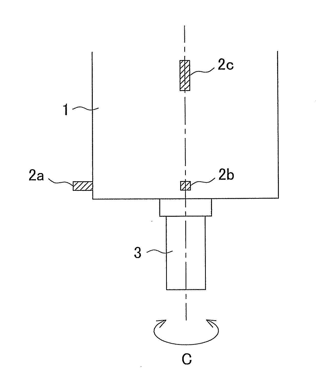
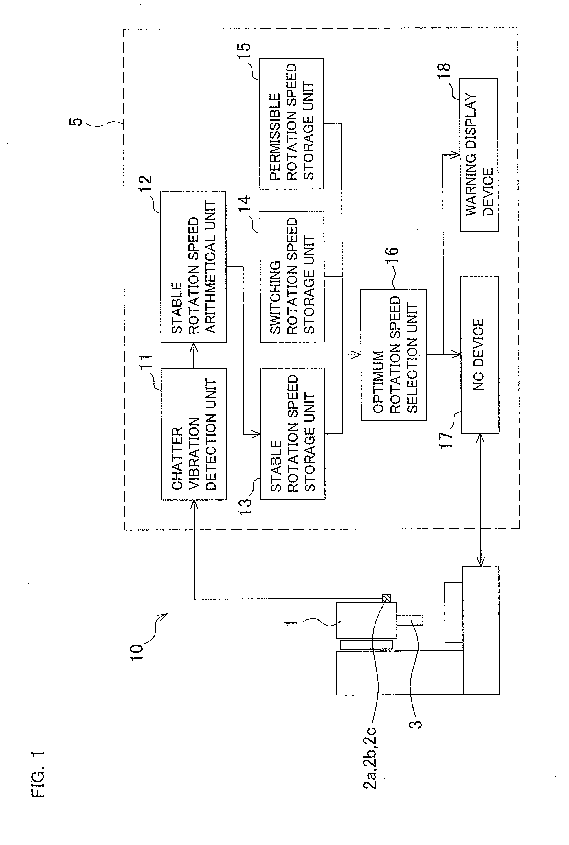
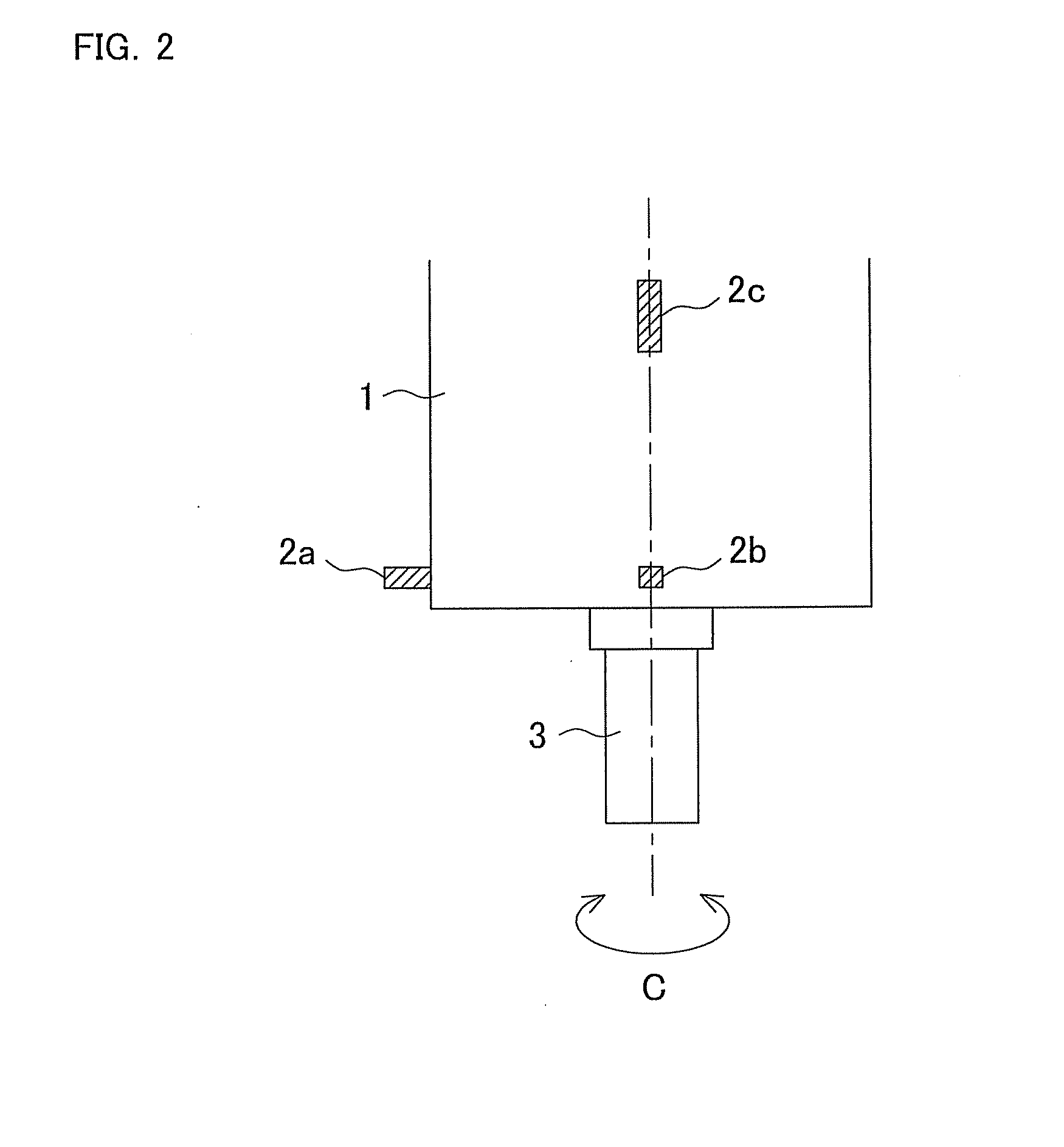
[0024]A vibration suppressing device 10 is a device for suppressing “chatter vibrations” occurring at a main spindle (rotary shaft) 3 provided in a rotary shaft housing 1 in such a manner that the main spindle 3 is rotatable about a C-axis. The vibration suppressing device 10 includes vibration sensors 2a-2c configured to detect time-domain vibrational accelerations (i.e., vibrational accelerations on the time axis) that are characteristics possessed by vibrations occurring at the rotating main spindle 3. Further, the vibration suppressing device 10 includes a control device 5 configured to analyze the outputs of the vibration sensors 2a-2c, determine the presence or absence of the “chatter vibrations”, and control the rotation speed of the main spindle 3 based on the results of determination. Inside t...


PUM

PropertyMeasurementUnit
rotation speedsaaaaaaaaaa
rotation speedaaaaaaaaaa
chatter frequencyaaaaaaaaaa

Abstract

In a machine tool having a rotary shaft for use in rotating a tool or a workpiece, a plurality of stable rotation speeds at which the chatter vibrations are expected to be suppressed, and at least one switching rotation speed across which a dynamic characteristic of a rotary shaft system changes are stored. The plurality of stable rotation speeds may be determined from chatter vibrations detected using a vibration detection unit. Optimum rotation speed that is a rotation speed to which a rotation speed of the rotary shaft is changeable without crossing the switching rotation speed is selected from the plurality of stable rotation speeds, and the rotation speed of the rotary shaft is changed to the optimum rotation speed. Thus, chatter vibrations generated during rotation of the rotary shaft can be suppressed effectively.

Description

BACKGROUND OF THE INVENTION[0001]This application claims the benefit of Japanese Patent Application Number 2010-230685 filed on Oct. 13, 2010, the entirety of which is incorporated by reference.TECHNICAL FIELD[0002]The present invention relates to a vibration suppressing method for use in a machine tool which performs a machining operation on a workpiece with a tool while rotating the tool or the workpiece, for suppressing chatter vibrations generated during the machining operation, and a vibration suppressing device for executing such a vibration suppressing method.BACKGROUND ART[0003]An example of hitherto-known vibration suppressing methods for use in a machine tool which performs a machining operation with a rotary shaft (i.e., main spindle) being rotated is disclosed in Japanese Patent Application Laid-Open Publication 2003-340627 In this vibration suppressing method, in order to suppress chatter vibrations which would cause deterioration in the accuracy of a finished surface o...

Claims


Application Information

Patent Timeline
Patent Type & Authority Applications(United States)
IPC IPC(8): B23Q15/12
CPCG05B19/404Y10T409/30084B23Q15/007G05B2219/42344Y10T409/304312Y10T409/306832Y10T409/307224
Inventor UENO, HIROSHI
Owner OKUMA CORP
Why Eureka
Try Eureka