Dynamic switching thermoelectric thermal management systems and methods

Inactive Publication Date: 2012-04-26
PURDUE RES FOUND INC
View PDF17 Cites 18 Cited by
  • Summary
  • Abstract
  • Description
  • Claims
  • Application Information

AI Technical Summary

Benefits of technology

[0007]Thermoelectric effects include the direct conversion of temperature differences to electric potential differences (Seebeck effect) and electric potential differences to temperature differences (Peltier effect). The names are derived from the independent discoveries of French physicist Jean Charles Athanase Peltier and Estonian-German physicist Thomas Johann Seebeck. In 1821, Seebeck found that if two dissimilar metals are connected and there is a temperature difference across the junction, a voltage will develop across the junction. The Seebeck effect forms the basis of the power generation function of a thermoelectric device. In 1834, Peltier discovered the inverse Seebeck effect where if a current is flowing through two dissimilar metals connected at a junction, a temperature gradient will develop across the junction, which leads to a heat flux. The Peltier effect forms the basis of the cooling function of a thermoelectric device. In the 1900's, researchers found efficient thermoelectric materials that possess large Seebeck coefficients

Problems solved by technology

Moreover, the powered cooling devices need additional energy to operate.
However, if the desir

Method used


Image

  • Dynamic switching thermoelectric thermal management systems and methods
  • Dynamic switching thermoelectric thermal management systems and methods
  • Dynamic switching thermoelectric thermal management systems and methods

Examples


Embodiment Construction

[0016]For the purposes of promoting an understanding of the principles of the novel technology, reference will now be made to the embodiments described herein and illustrated in the drawings and specific language will be used to describe the same. It will nevertheless be understood that no limitation of the scope of the novel technology is thereby intended, such alterations and further modifications in the illustrated devices and methods, and such further applications of the principles of the novel technology as illustrated therein being contemplated as would normally occur to one skilled in the art to which the novel technology relates.

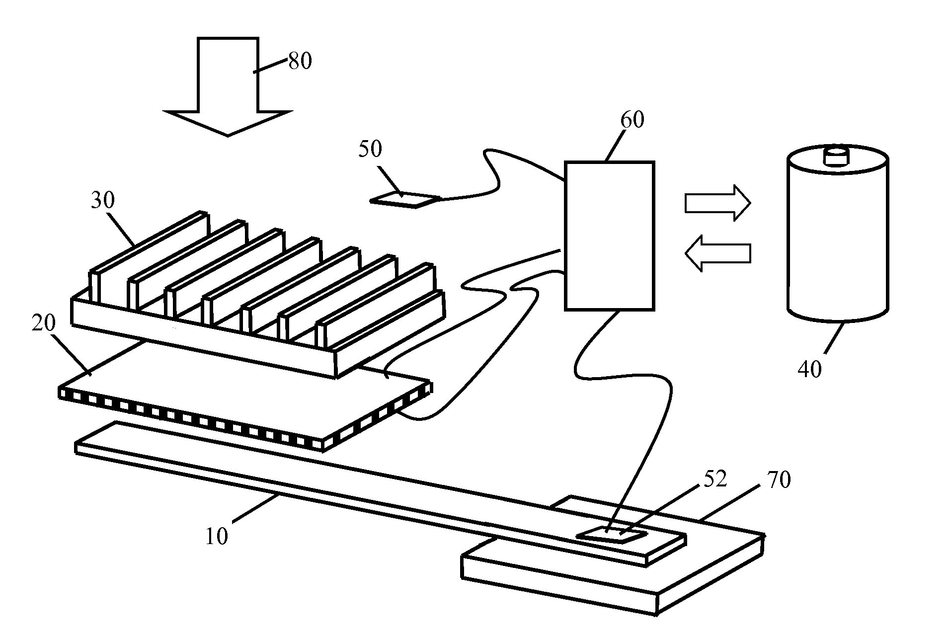
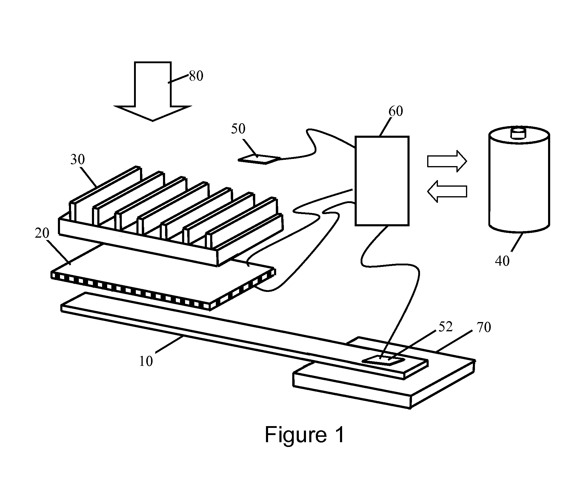
[0017]FIG. 1 illustrates an exemplary embodiment of a thermoelectric thermal management system. The components in FIG. 1 are not necessarily drawn to scale, the emphasis instead being to clearly illustrate the principles of the embodiment of the thermoelectric thermal management system. This embodiment of the thermal management system includes a heat...


PUM


Abstract

A dynamic switching thermoelectric thermal management system and method is disclosed. The thermal management system includes a heat dissipation device, a thermoelectric module, an ambient temperature sensor, a heat source temperature sensor, an energy storage device and a controller. One side of the thermoelectric module is thermally coupled to the heat source and another side is thermally coupled to the heat dissipation device. The controller periodically samples the temperature sensors and dynamically switches the thermoelectric module between a power generation mode in which the thermoelectric module uses the temperature difference between the heat source and ambient to charge the energy storage device, a cooling mode in which the thermoelectric module is powered to create a voltage difference across the thermoelectric module to cool the heat source, and an idle mode. The thermal management system can be integrated into a portable electronic device, for example a portable computing device.

Description

CROSS-REFERENCE TO RELATED APPLICATIONS[0001]This application claims the benefit of U.S. Provisional Application Ser. No. 61 / 405,891, filed on Oct. 22, 2010, entitled “Dynamic Switching Thermoelectric Thermal Management Systems and Methods” which is incorporated herein by reference.BACKGROUND AND SUMMARY[0002]This invention relates to a dynamic switching thermal management system and more particularly to a temperature controlling system using a thermoelectric module and an energy storage device.[0003]For most heat generating systems, a large fraction of energy is dissipated as waste heat. As a result, the temperatures of the heat sources in the system are elevated. Most of these heat sources need passive or powered heat dissipation devices to extract the waste heat and maintain the critical components of the system within a desired temperature range. Moreover, the powered cooling devices need additional energy to operate.[0004]Prior systems have used a fan driven heat sink assembly ...

Claims


Application Information

Patent Timeline
IPC IPC(8): F25B21/02
CPCF25B21/02F25B2700/2107F25B2321/021F25B49/00
Inventor WANG, YUEFENGSANDS, TIMOTHY DAVID
Owner PURDUE RES FOUND INC
Why Eureka
Try Eureka