
Switch with reduced contacting areas between actuator and insulative housing

a technology of actuator and insulating housing, applied in the field of switches, can solve the problems of difficult button driving and low profile of push-button switches, and achieve the effect of greatly reducing the contact area of the actuator and the corresponding inner surfa

Active Publication Date: 2012-04-26
HON HAI PRECISION IND CO LTD
View PDF1 Cites 0 Cited by
  • Summary
  • Abstract
  • Description
  • Claims
  • Application Information

AI Technical Summary

Benefits of technology

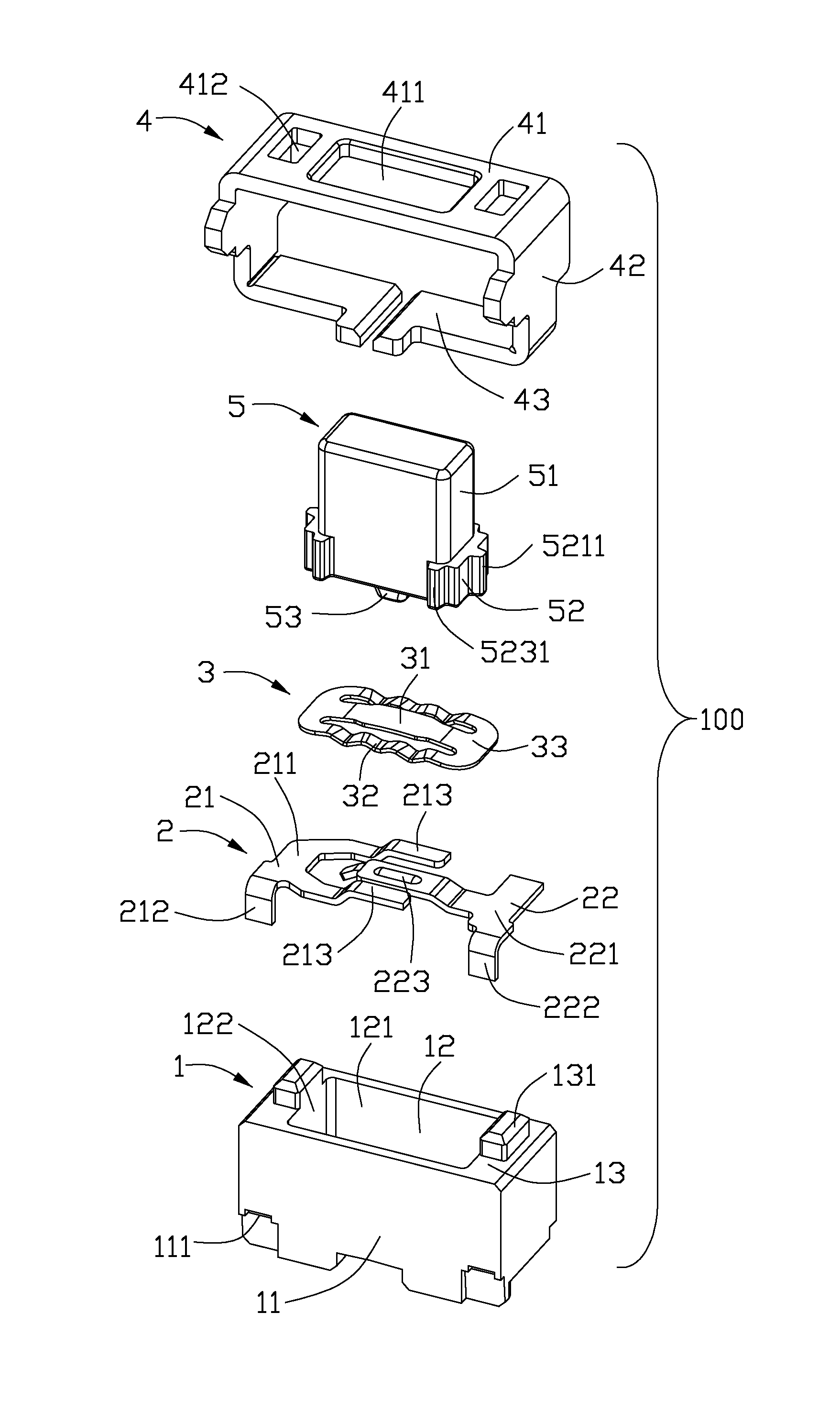
[0007]The present invention provides a switch including an insulative housing, at least one fixed contact retained in the insulative housing, a movable contact mounted to the insulative housing for alternatively contacting the at least one fixed contact, and an actuator slidably assembled to the insulative housing along a vertical direction. The insulative housing includes a plurality of peripheral walls and a receiving cavity enclosed by the peripheral walls. Each peripheral wall includes an inner surface exposed to the receiving cavity. The movable contact is located above the at least one fixed contact. The actuator includes a bottom portion received in the receiving cavity, a bottom operator for deforming of the moveable contact and a button extending oppositely to the bottom operator. The bottom portion includes a first side wall and a first rib protruding sidewardly from the first side wall. The first rib is slidable against a first inner surface of the peripheral walls while the first side wall is separated from the first inner surface by a gap which is located along a horizontal direction perpendicular to the vertical direction. As a result, contacting areas of the actuator and corresponding inner surface are greatly reduced, and soldering materials, such as flux, originally influencing movement of the actuator can be avoided.

Problems solved by technology

However, since the profile of the push-button switch is low, during soldering process, soldering materials, such as flux, may easily enter into the opening and be deposited on the inner surfaces of the insulative housing.
Under this condition, it may be difficult to drive the button because of large friction force coming from large contacting areas therebetween.

Method used


Image

  • Switch with reduced contacting areas between actuator and insulative housing
  • Switch with reduced contacting areas between actuator and insulative housing
  • Switch with reduced contacting areas between actuator and insulative housing

Examples


Embodiment Construction

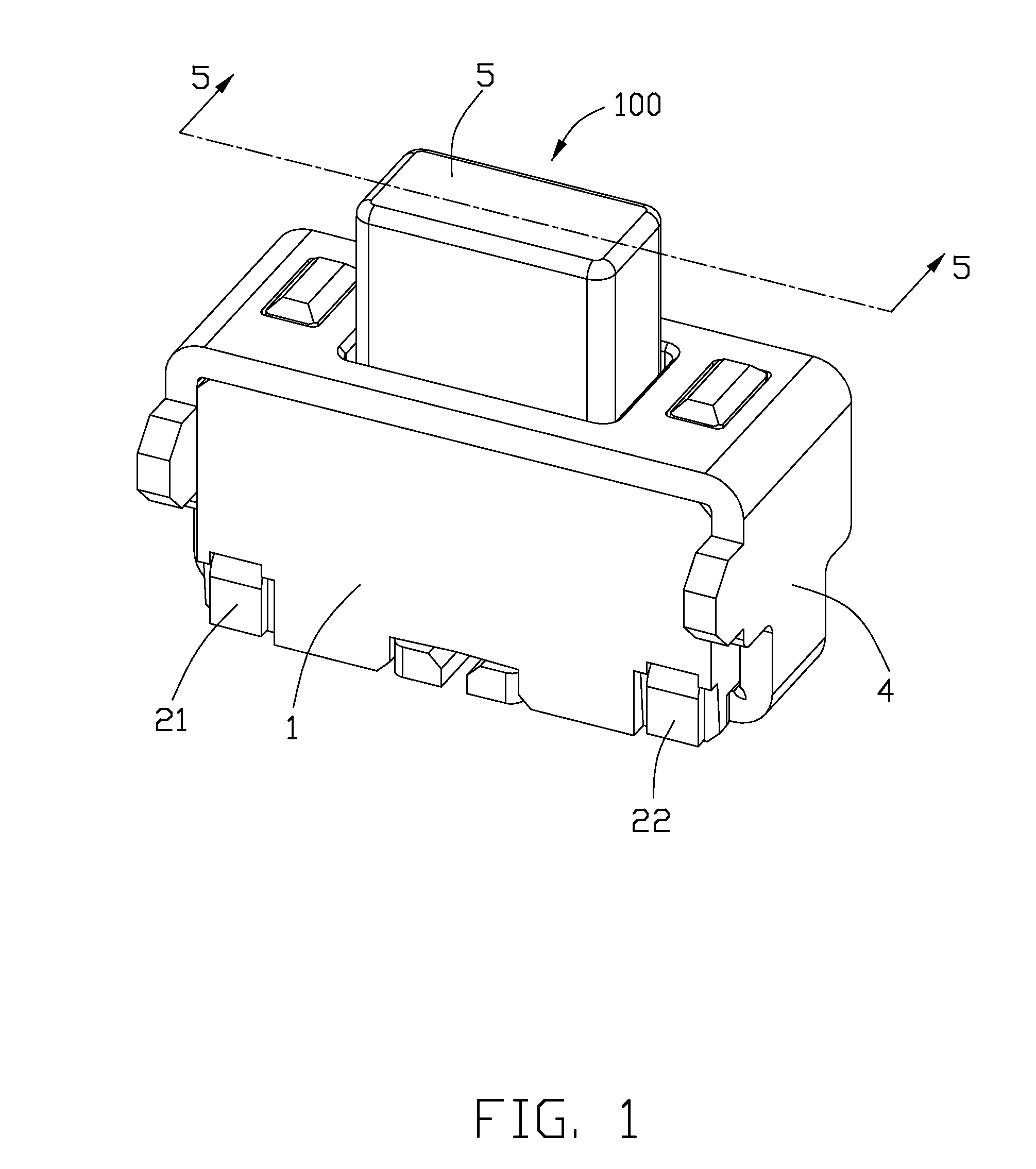
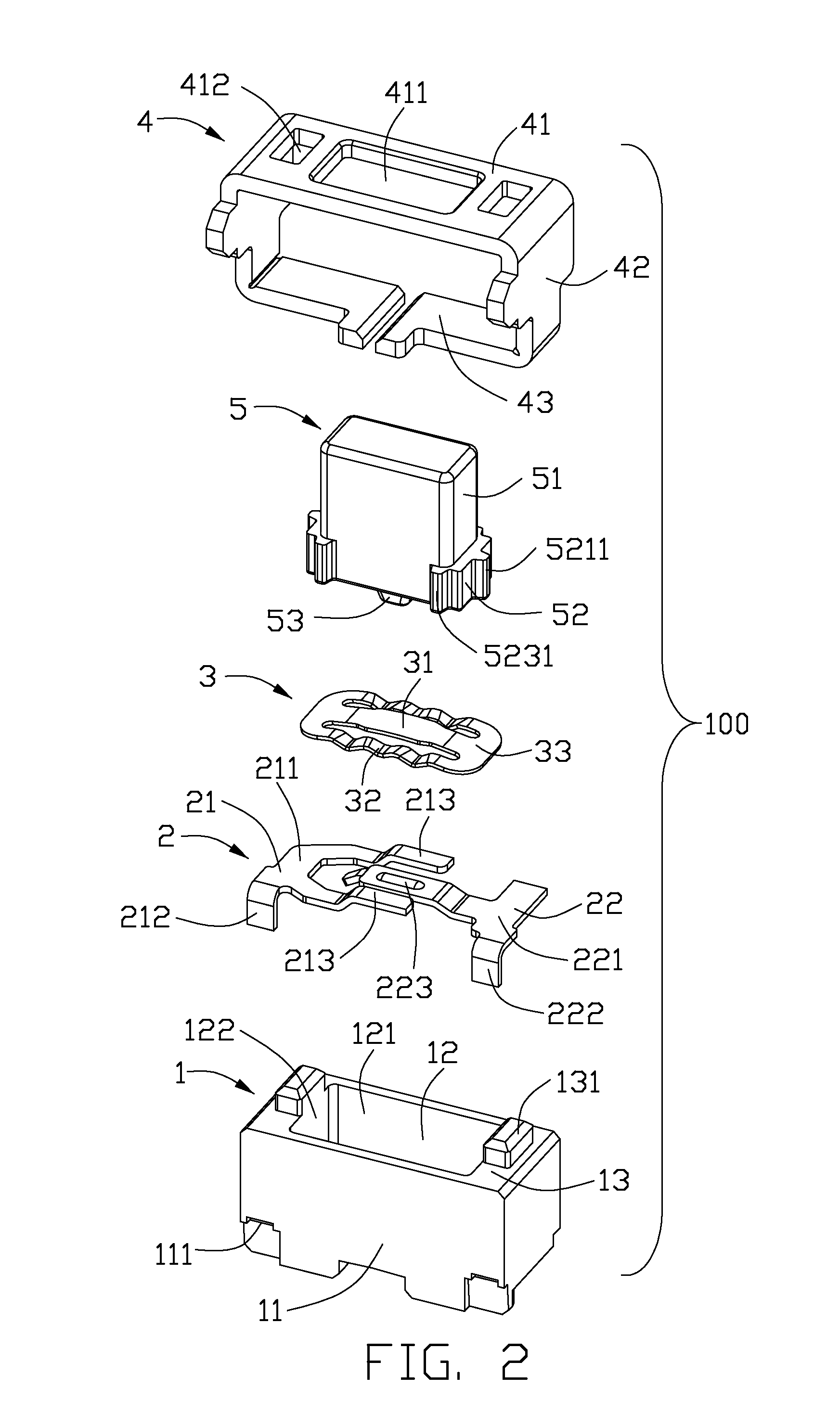
[0015]Reference will now be made to the drawing figures to describe the preferred embodiment of the present invention in detail. FIGS. 1 and 2 illustrate a kind of push-button switch 100 usually used in electronic devices. The switch 100 includes an insulative housing 1, a pair of fixed contacts 2 fixed in the insulative housing 1, a movable contact 3 installed in the insulative housing 1, an actuator 5 partly received in the insulative housing 1, and a top shell 4 enclosing the insulative housing 1.

[0016]Referring to FIGS. 2 to 5, the insulative housing 1 is box-shaped and includes a bottom wall (not labeled) and four side walls 11 extending upwardly from the bottom wall to jointly forming a receiving cavity 12. Each side wall 11 includes an inner surface 121 or 122 exposed to the receiving cavity 12. A pair of the opposite side walls 11 include a pair of locking blocks 131 extending upwardly therefrom for locking with the top shell 4. Besides, the insulative housing 1 defines a pl...


PUM


Abstract

A switch includes an insulative housing, a fixed contact, a movable contact and an actuator. The insulative housing defining a receiving cavity enclosed by a number of peripheral walls each of which includes an inner surface exposed to the receiving cavity. The actuator includes a bottom portion slidably received in the receiving cavity, a bottom operator for deforming of the moveable contact and a button. The bottom portion includes a first side wall and a first rib protruding sidewardly therefrom. The first rib is slidable against a first inner surface of the peripheral walls while the first side wall is separated a distance from the first inner surface. As a result, contacting areas of the actuator and corresponding inner surface are greatly reduced, and soldering materials, such as flux, originally influencing movement of the actuator can be avoided.

Description

BACKGROUND OF THE INVENTION[0001]1. Field of the Invention[0002]The present invention relates to a switch, and more particularly to a switch with reduced contacting areas between an actuator and an insulative housing during sliding.[0003]2. Description of Related Art[0004]Push-button switch is widely used in electronic devices via pressing its movable part to connect or disconnect internal circuits. Japanese Patent No. 4246119, issued to ALPS ELECTRIC CO., LTD. on Apr. 2, 2009 discloses a conventional push-button switch including an insulative housing, a frame enclosing the insulative housing, a plurality of contacts installed in the insulative housing and a button. The insulative housing defines an opening formed by a plurality of side walls for receiving a bottom portion of the button. Each side wall includes an inner surface exposed to the opening. When the button is pressed to move downwardly, most outer surfaces of the bottom portion slide against the inner surfaces of the insu...

Claims


Application Information

Patent Timeline
IPC IPC(8): H01H13/04
CPCH01H13/04
Inventor WANG, YONG-JIASUN, LIANG
Owner HON HAI PRECISION IND CO LTD
Learn More