Image decoding device, image coding device, image decoding method, image coding method, program, and integrated circuit

a decoding device and image technology, applied in signal generators with optical-mechanical scanning, color televisions with bandwidth reduction, etc., can solve the problems of increasing bit rate, reducing compression rate, image decoding device cannot reference decoding information, etc., and achieve smooth parallel processing

Inactive Publication Date: 2012-04-26
PANASONIC INTELLECTUAL PROPERTY MANAGEMENT CO LTD
View PDF7 Cites 32 Cited by
  • Summary
  • Abstract
  • Description
  • Claims
  • Application Information

AI Technical Summary

Benefits of technology

[0061]According to the present invention, the spatial dependence across the boundary between the slices is used and therefore the parallel processing is executed smoothly.

Problems solved by technology

For this reason, the image coding device and the image decoding device compliant with variable-length coding cannot employ parallel processing with which the processing speed is increased and, therefore, have to speed up the processing by increasing an operating frequency.
However, when the picture is divided into slices, the image decoding device cannot reference to decoding information across a boundary between the slices.
That is, the conventional image coding device and the conventional decoding device cannot use the correlation between data in the same picture, which causes a reduction in the compression rate.
Moreover, this results in increasing the bit rate and deteriorating the image quality.
For this reason, the start of the processing performed by the PE1 for the MB 0 is significantly delayed, thereby reducing efficiency.

Method used


Image

  • Image decoding device, image coding device, image decoding method, image coding method, program, and integrated circuit
  • Image decoding device, image coding device, image decoding method, image coding method, program, and integrated circuit
  • Image decoding device, image coding device, image decoding method, image coding method, program, and integrated circuit

Examples


embodiment 1

[1-1. Overview]

[0129]Firstly, an overview of an image decoding device according to Embodiment 1 of the present invention is described.

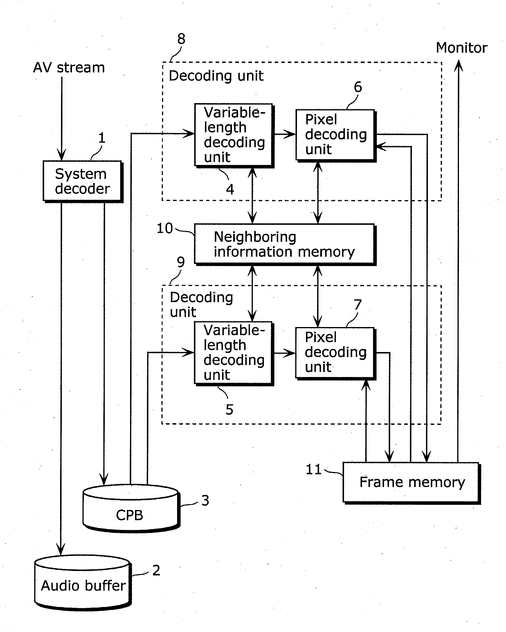
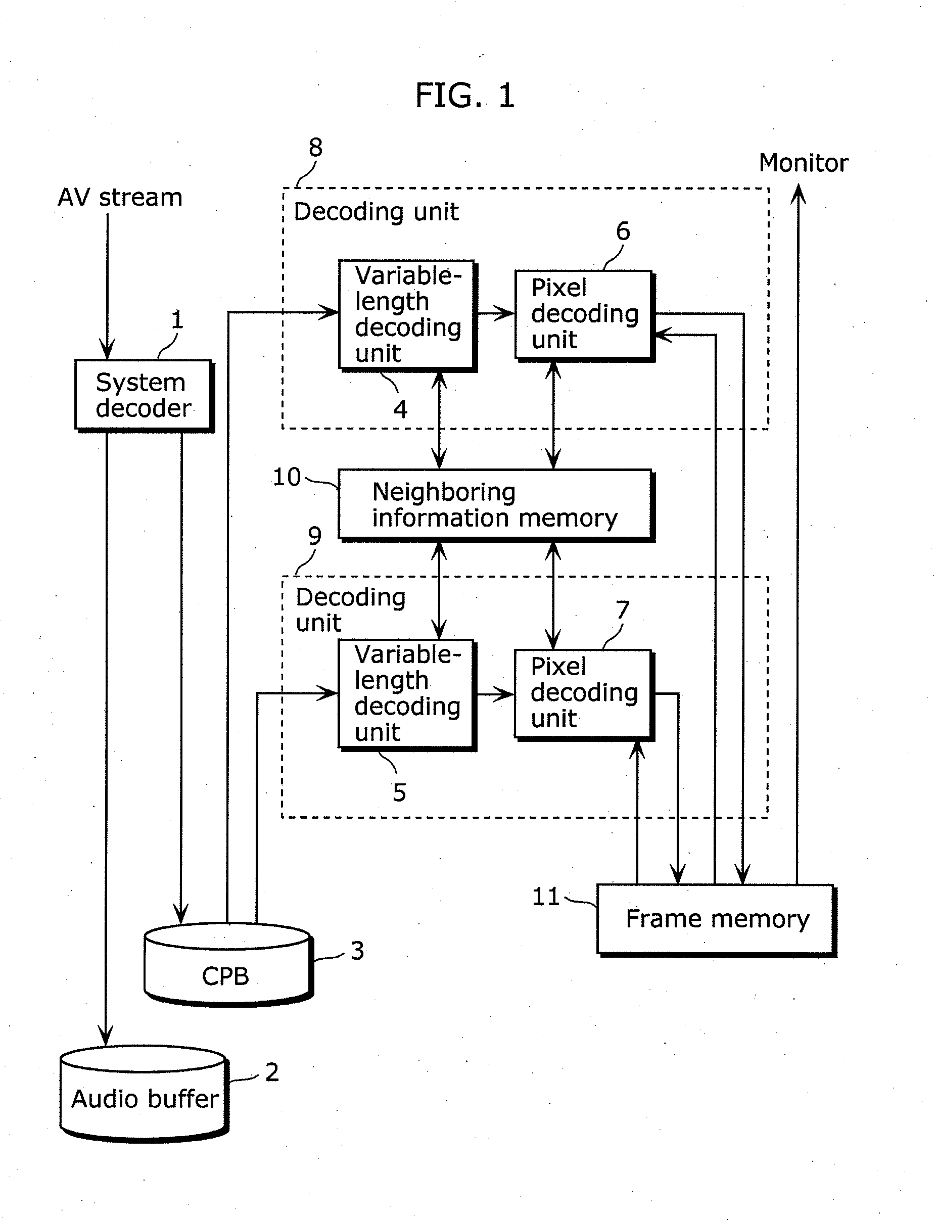
[0130]The image decoding device according to Embodiment 1 of the present invention reads a video stream separated from an AV-multiplexed stream by a system decoder, using a plurality of decoding units. The video stream is previously constructed so as be read by the decoding units. The decoding units execute the decoding process in synchronization with each other, by reference to each other's partial decoding result via a neighboring information memory.

[0131]This is the overview of the image decoding device according to Embodiment 1.

[1-2. Configuration]

[0132]Next, a configuration of the image decoding device according to Embodiment 1 is described.

[0133]FIG. 1 is a block diagram showing the configuration of the image decoding device according to Embodiment 1. The image decoding device in Embodiment 1 includes a system decoder 1, a coded picture buffer (...

embodiment 2

[2-1. Overview]

[0239]Next, an overview of an image decoding device according to Embodiment 2 of the present invention is described.

[0240]Embodiment 2 employs context adaptive variable length coding (CAVLC) adopted by the H.264 standard as one of the variable-length coding methods.

[0241]This is the overview of the image decoding device according to Embodiment 2.

[2-2. Configuration]

[0242]A configuration of the image decoding device according to Embodiment 2 is identical to the configuration according to Embodiment 1.

[2-3. Operation]

[0243]Next, an operation performed in Embodiment 2 is described with reference to FIG. 8 which is used for describing the operation in Embodiment 1. The operation of Embodiment 2 is different from that of Embodiment 1 in a variable-length-decoding arithmetic process (S111).

[0244]FIG. 19 is a diagram showing an example of a coded table in Embodiment 2. In FIG. 19, nC represents the number of non-zero coefficients in a neighboring macroblock.

[0245]As shown by...

embodiment 3

[3-1. Overview]

[0258]Next, an overview of an image decoding device according to Embodiment 3 of the present invention is described.

[0259]In Embodiment 3, a variable-length coding method is used for arithmetic coding. A variable-length decoding unit includes an arithmetic decoding unit, which allows the image decoding device in Embodiment 3 to be capable of arithmetic decoding.

[0260]This is the overview of the image decoding device according to Embodiment 3.

[3-2. Configuration]

[0261]Next, a configuration of the image decoding device according to Embodiment 3 is described.

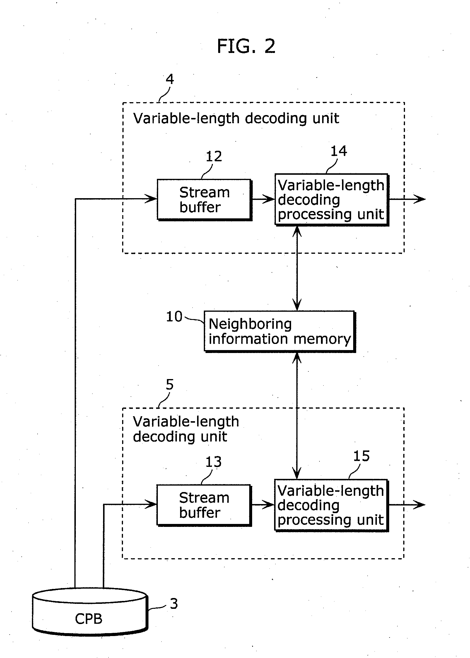
[0262]FIG. 20 is a block diagram showing configurations of the variable-length decoding units included in the image decoding device in Embodiment 3. Components in FIG. 20 which are identical to those in FIG. 2 are not explained again here. The variable-length decoding unit 4 in Embodiment 3 supports arithmetic coding, and includes an arithmetic decoding unit 23 which performs arithmetic decoding and a de-binarization...


PUM


Abstract

An image decoding device and an image coding device are each capable of using spatial dependence across a boundary between slices to smoothly execute parallel processing. The image decoding device includes: a first decoding unit (801) decoding a block in a first slice; a second decoding unit (802) decoding a block in a second slice; and a first storage unit (811) storing inter-slice neighboring information (i) generated by decoding a boundary block included in the first slice and adjacent to the second slice and (ii) referenced when a boundary neighboring block included in the second slice and adjacent to the boundary block is decoded. The first decoding unit (801) generates the inter-slice neighboring information by decoding the boundary block and stores the generated information into the first storage unit (811). The second decoding unit (802) decodes the boundary neighboring block by reference to the stored inter-slice neighboring information.

Description

TECHNICAL FIELD[0001]The present invention relates to image decoding devices for decoding coded images and image coding devices for coding images, and particularly to an image decoding device which performs parallel decoding and an image coding device which performs parallel coding.BACKGROUND ART[0002]A conventional image coding device for coding a video sequence divides each picture included in the video sequence into macroblocks, and performs coding for each of the macroblocks. The size of a macroblock is 16 pixels high and 16 pixels wide. Then, the conventional image coding device generates a coded stream, that is, a coded video sequence. After this, a conventional image decoding device decodes this coded stream on a macroblock-by-macroblock basis to reproduce the pictures of the original video sequence.[0003]The conventional coding methods include the International Telecommunication Union Telecommunication Standardization Sector (ITU-T) H.264 standard (see Non Patent Literature ...

Claims


Application Information

Patent Timeline
Patent Type & Authority Applications(United States)
IPC IPC(8): H04N7/26
CPCH04N19/436
Inventor TANAKA, TAKESHIYOSHIMATSU, NAOKI
Owner PANASONIC INTELLECTUAL PROPERTY MANAGEMENT CO LTD
Why Eureka
Try Eureka